Parking lock device for transmission
- Summary
- Abstract
- Description
- Claims
- Application Information
AI Technical Summary
Benefits of technology
Problems solved by technology
Method used
Image
Examples
Embodiment Construction
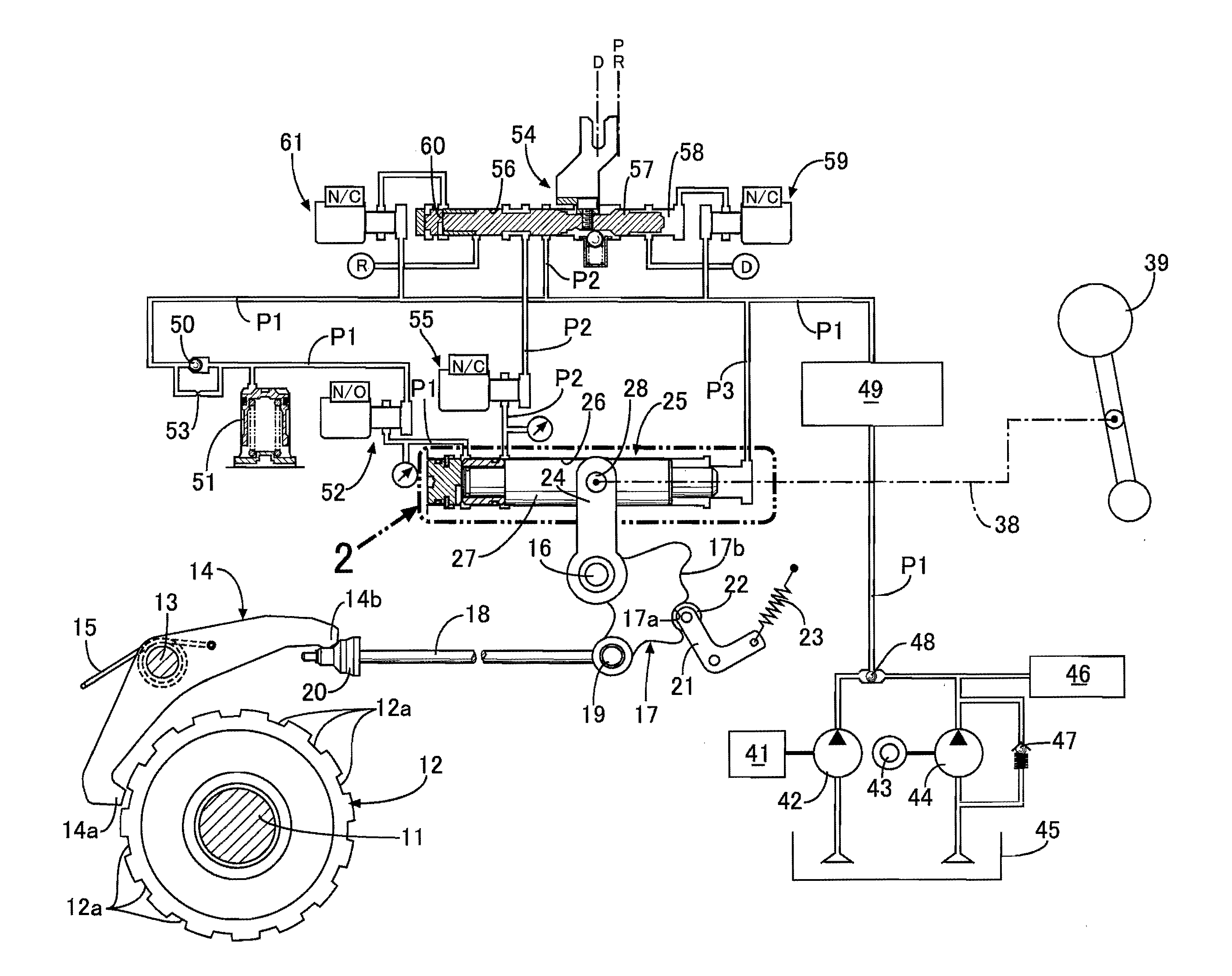
[0031]Descriptions will be hereinbelow provided for an embodiment of the present invention on the basis of FIG. 1 to FIG. 7.
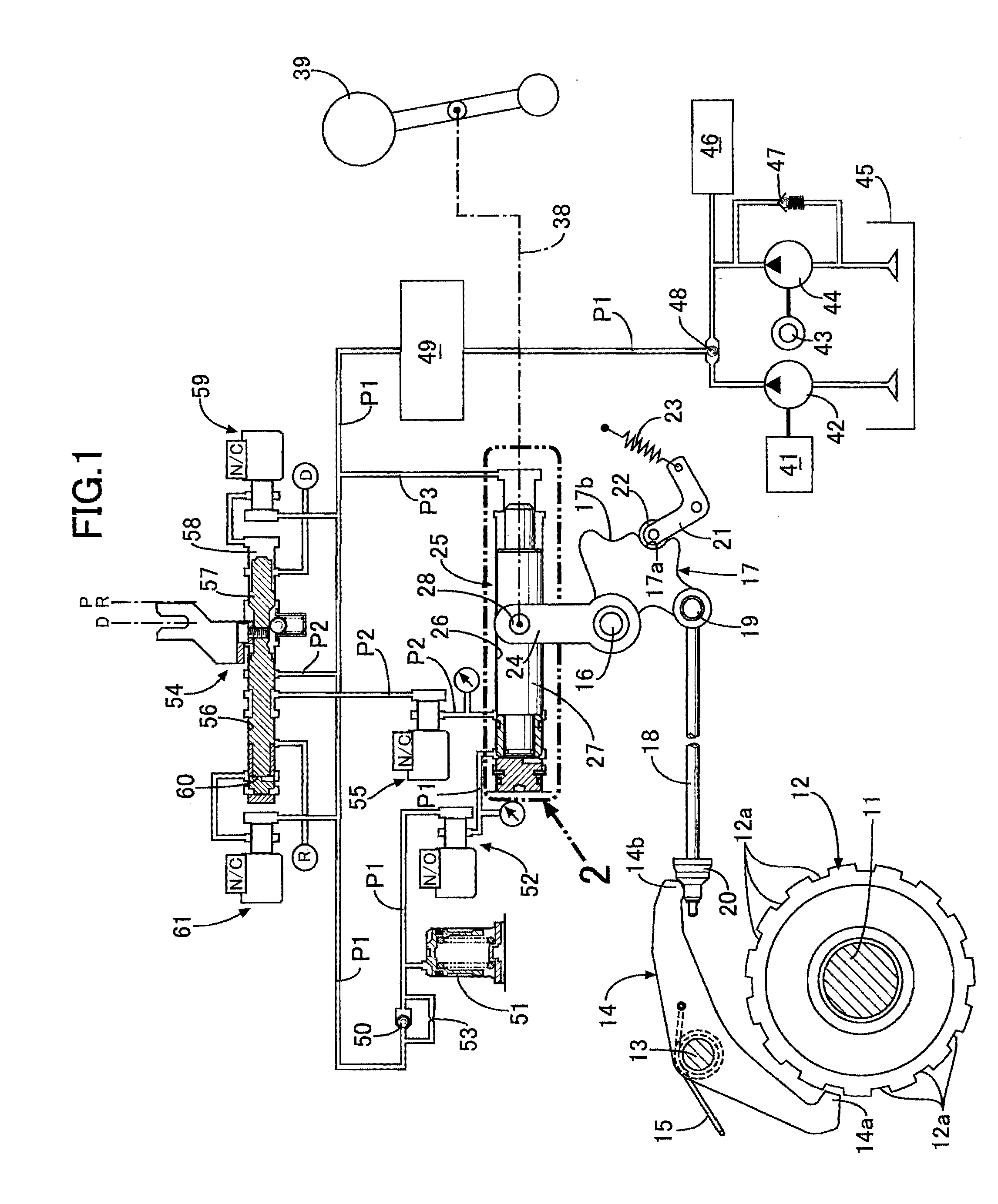
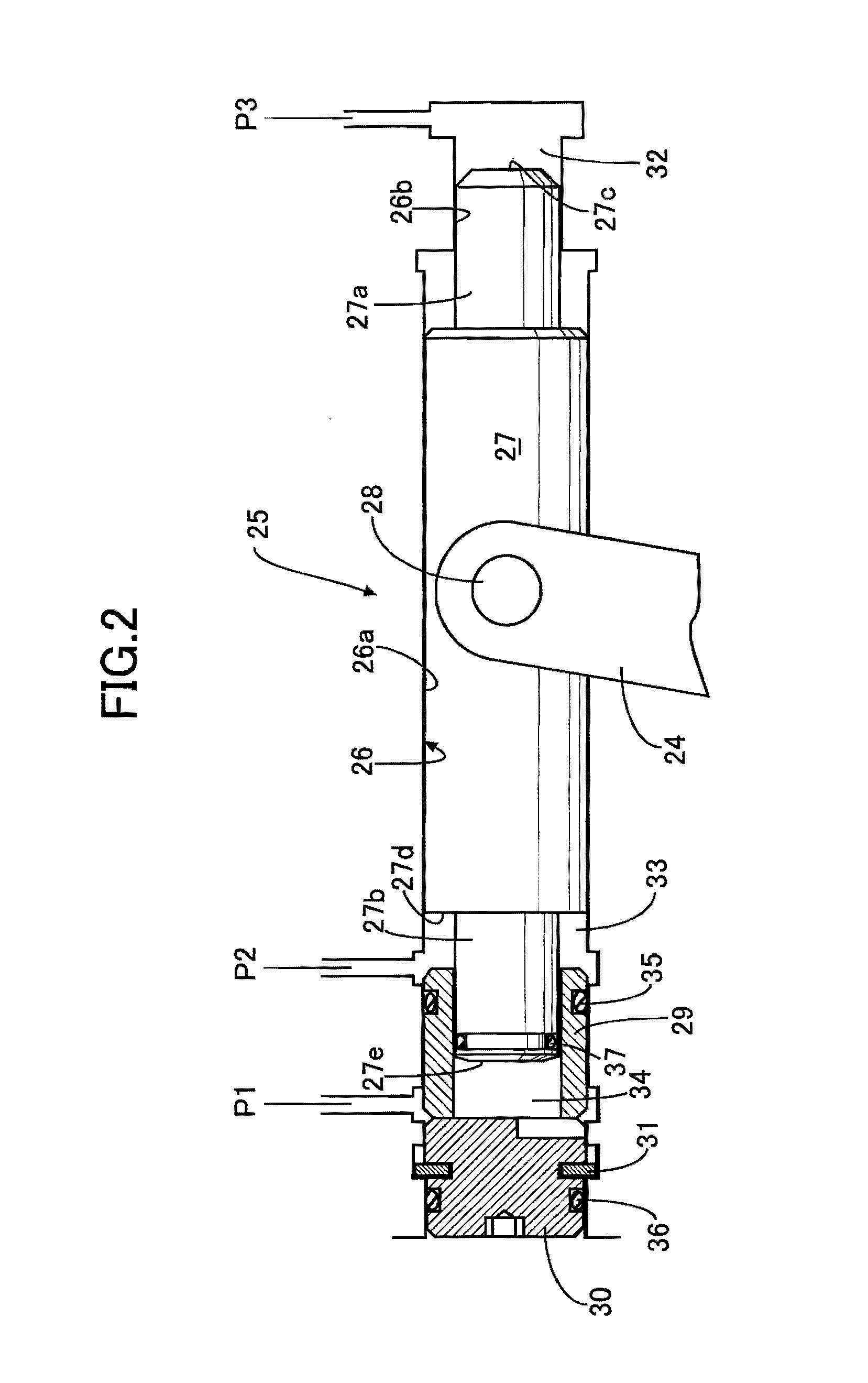
[0032]To begin with, the structure of the parking lock device will be described on the basis of FIG. 1 and FIG. 2.
[0033]A parking gear 12 is fixed to a gearshift shaft 11 of a transmission. A locking claw 14a provided at one end of a parking pawl 14 pivotably supported by a spindle 13 is biased by a spring 15 in a detaching direction from tooth grooves 12a of the parking gear 12. One end of a parking rod 18 is pivotably supported by a detent plate 17, which is pivotably supported by a spindle 16, by use of a pin 19. A cone-shaped cam 20 provided at the other end of the parking rod 18 comes into contact with a cam follower 14b provided at the other end of the parking pawl 14. A detent roller 22 provided at one end of a swingable arm 21 is biased by a spring 23 so as to be engaged with one of two recessed portions 17a, 17b of the detent plate 17. A link 24 pivota...
PUM
 Abstract
Description
Claims
Application Information
 - R&D
- Intellectual Property
- Life Sciences
- Materials
- Tech Scout
- Unparalleled Data Quality
- Higher Quality Content
- 60% Fewer Hallucinations
Browse by: Latest US Patents, China's latest patents, Technical Efficacy Thesaurus, Application Domain, Technology Topic, Popular Technical Reports.
© 2025 PatSnap. All rights reserved.Legal|Privacy policy|Modern Slavery Act Transparency Statement|Sitemap|About US| Contact US: help@patsnap.com


