
Pneumatic ejector pin clamp

A thimble, air pressure technology, applied in the field of workpiece accessories, can solve the problems of affecting the clamping effect, easy to shake up and down, insufficient clamping force, etc.

Inactive Publication Date: 2015-03-11
CHANGZHOU HOUXIAO YUHENG CURTAIN WALL
View PDF0 Cites 2 Cited by
  • Summary
  • Abstract
  • Description
  • Claims
  • Application Information

AI Technical Summary

Problems solved by technology

[0002] The traditional thimble fixture controls the position of the thimble manually. Due to manual processing, it is easy to cause loosening due to insufficient clamping force or damage to the workpiece due to excessive clamp

Method used


Image

  • Pneumatic ejector pin clamp

Examples


Embodiment Construction

[0010] The present invention will be further described in detail below in conjunction with the accompanying drawings and specific embodiments.

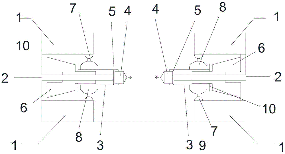
[0011] like figure 1 As shown, the air pressure thimble clamp includes four fixed blocks 1 located at the top corners, an air pressure thimble is arranged between the upper and lower two fixed blocks 1, and the air pressure thimble includes air passages 2 on both sides, The air passage 2 communicates with the cylinder 3, and the other side of the cylinder 3 is provided with a collet 4, and the collet 4 is connected in the cylinder 3 through an airtight ring 5, and the outer periphery of the air pressure thimble is provided with The expansion ring 6, the section of the expansion ring 6 is trapezoidal, and part of the upper bottom surface of the trapezoidal section extends into the cylinder 3.

[0012] According to the above structure, the collet moves back and forth through the air pressure in the air circuit in the cylinder. When the...


PUM


Abstract

The invention relates to a pneumatic ejector pin clamp, which comprises four fixing blocks, wherein the fixing blocks are positioned at the top corner, pneumatic ejector pins are arranged between the upper fixing blocks and the lower fixing blocks, and respectively comprise air paths and an expansion ring, the air paths are positioned at the two sides, and are communicated with an air cylinder, the other side of each air cylinder is provided with a clamping head, each clamping head is connected with the interior of the corresponding air cylinder through a sealed air ring, each expansion ring is arranged at the periphery of the corresponding pneumatic ejector pin, the cross section of each expansion ring is in a trapezoid shape, and one part of the upper bottom surface of each trapezoidal cross section extends into the corresponding air cylinder. The pneumatic ejector pin clamp has the advantages that each ejector pin is pushed by the hydraulic force, so the corresponding ejector pin is guaranteed to effectively clamp a workpiece; the hydraulic air cylinder is fixed by a balance and stable structure, so the swinging of each air cylinder is effectively avoided, and the practicality is realized.

Description

technical field [0001] The invention relates to the field of workpiece accessories, in particular to a pneumatic thimble clamp. Background technique [0002] The traditional thimble fixture controls the position of the thimble manually. Due to manual processing, it is easy to cause loosening due to insufficient clamping force or damage to the workpiece due to excessive clamping force. There is also the use of hydraulic pressure to push the thimble, while the traditional The hydraulic drive has an unstable hydraulic cylinder, which is easy to shake up and down, which affects the clamping effect. Contents of the invention [0003] The purpose of the present invention is to propose a pneumatic thimble clamp, which uses hydraulic power to push the thimble to ensure that the thimble can effectively clamp the workpiece, and at the same time fix the hydraulic cylinder with a balanced and stable structure, effectively preventing the cylinder from shaking. practicality. [0004] ...

Claims


Application Information

Patent Timeline
IPC IPC(8): B25B11/00
CPCB25B11/00
Inventor 孔立峰
Owner CHANGZHOU HOUXIAO YUHENG CURTAIN WALL
Learn More