
Inductive power transfer converter

a technology of inductive power transfer converter and converter, which is applied in the direction of transformer/inductance details, transformers, inductances, etc., can solve the problems of affecting the power conversion efficiency of power converters

Inactive Publication Date: 2014-07-03
ENPHASE ENERGY
View PDF2 Cites 9 Cited by
  • Summary
  • Abstract
  • Description
  • Claims
  • Application Information

AI Technical Summary

Benefits of technology

The present invention is about a method and device for converting IPT power. It has technical benefits that involve increased efficiency and power transfer. These improvements can be utilized in various applications to enhance the performance of IPT power transfer systems.

Problems solved by technology

Such variations in the load, detrimentally impacts the power conversion efficiency of the power converter.

Method used


Image

  • Inductive power transfer converter
  • Inductive power transfer converter
  • Inductive power transfer converter

Examples


Embodiment Construction

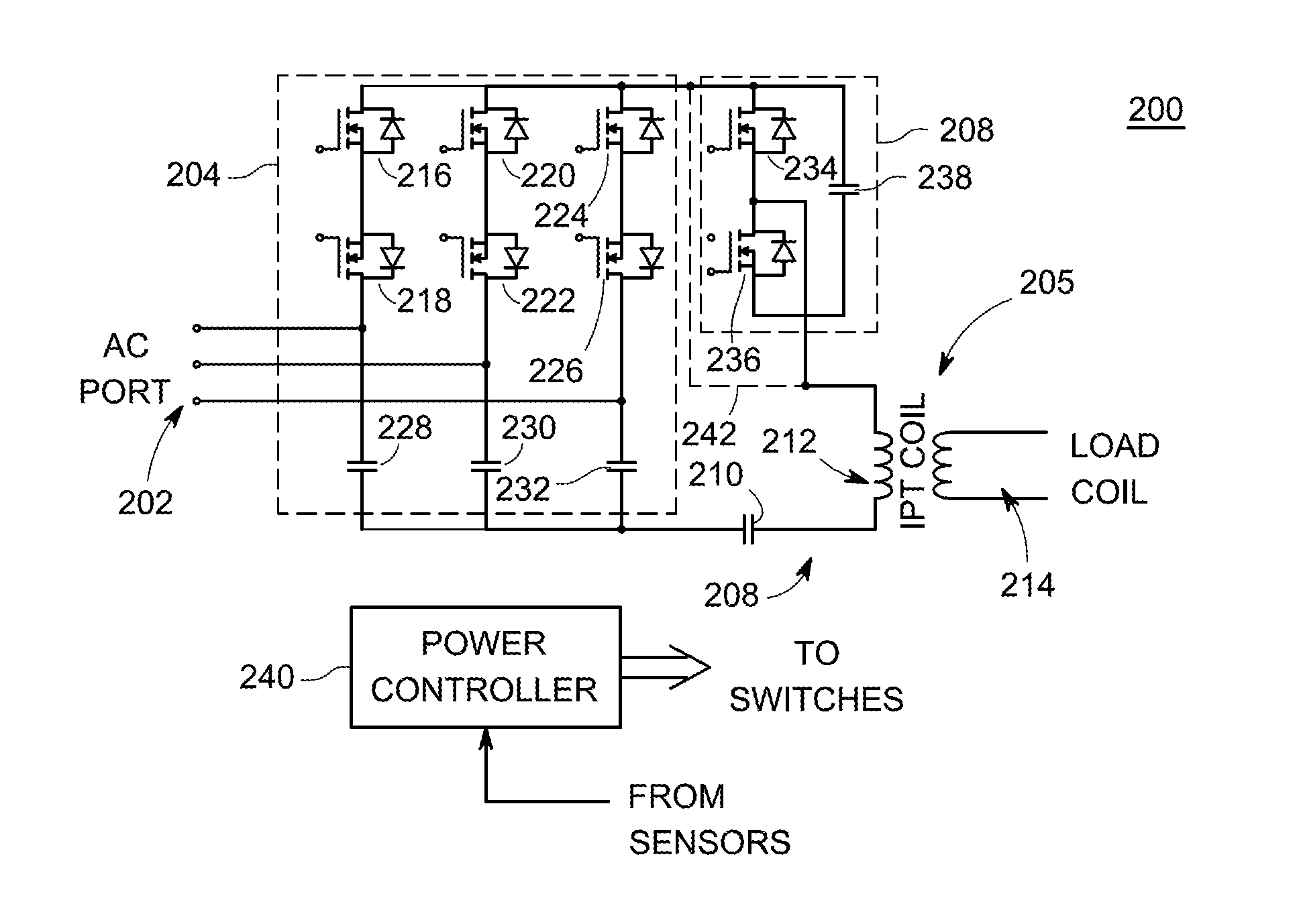
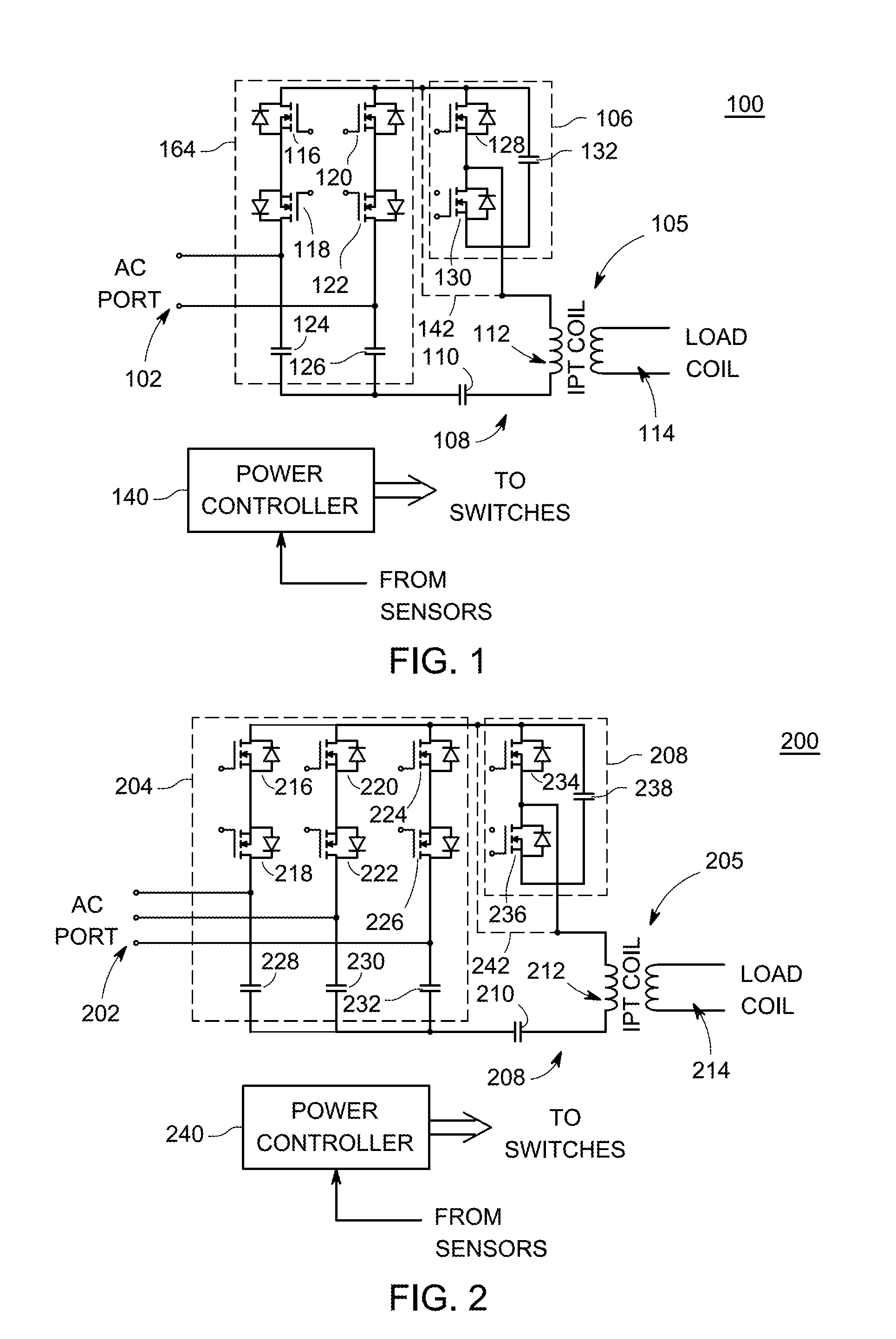
[0014]Embodiments of the present invention generally relate to an inductive power transfer (IPT) converter capable of bi-directional power transfer. The IPT converter comprises a bidirectional power converter coupled to an IPT coil. When a load coil is positioned proximate the IPT coil, power is coupled to a load (e.g., a battery of an electronic device) via inductive coupling between the IPT coil and the load coil. In addition, power may be coupled from the load (operating as a source of power) and converted to AC power by the same circuitry. In either direction, the IPT converter dynamically adjusts the power conversion to adapt to load variations and source variations to achieve the most efficient bi-directional power transfer.

[0015]FIG. 1 depicts a schematic for an exemplary single phase IPT power transfer converter 100 in accordance with one or more embodiments of the present invention. The schematic as described is an exemplary IPT converter (hereinafter, “converter”) 100 conv...


PUM


Abstract

A bidirectional inductive power transfer (IPT) power converter comprising a cycloconverter, coupled to an AC port, and a resonant circuit, coupled to the cycloconverter, for storing energy and coupling energy to an IPT port.

Description

CROSS-REFERENCE TO RELATED APPLICATIONS[0001]This application claims priority to U.S. Provisional Patent Application No. 61 / 747,359 filed on Dec. 30, 2012, which is incorporated by reference herein in its entirety.BACKGROUND[0002]1. Field[0003]Embodiments of the present invention generally relate to power conversion techniques and, more particularly, to efficient power conversion for inductive power transfer (IPT).[0004]2. Description of the Related Art[0005]Inductive Power Transfer (IPT) is the contactless transfer of power between two inductor coils. An IPT converter comprises an AC-DC power converter and an IPT coil that inductively couples DC power to a load coil. Applications for IPT include “wireless” charging of batteries in electric vehicles and portable devices (e.g., mobile phones, laptops, computer tablets, and the like), as well as wireless power transfer in mass transit systems (e.g., between mass transit vehicles for trains, subways, trolleys, and the like as well as c...

Claims


Application Information

Patent Timeline
IPC IPC(8): H02M5/458H02J5/00
CPCH02J5/005H02M5/4585H02M5/297Y02B70/10H02M1/0012H02M1/0058H02J50/12H02J5/00H02J7/02
Inventor HARRISON, MICHAEL J.
Owner ENPHASE ENERGY
Learn More