
Pedal beating apparatus for musical instruments

a pedal beating and musical instrument technology, applied in the field of pedal beating apparatuses for musical instruments, can solve the problems of bending the back of the hoop, not meeting the requirements of usability and convenience, and the method of clamping the drum hoop is tedious and time-consuming, and achieves the effect of quick clamping of different types of drum hoop

Active Publication Date: 2014-07-03
LIAO TSUN CHI
View PDF4 Cites 21 Cited by
  • Summary
  • Abstract
  • Description
  • Claims
  • Application Information

AI Technical Summary

Benefits of technology

The present invention is a pedal beating apparatus for musical instruments that allows quick and easy clamping of different types of drum hoops. The apparatus includes a pedal beating holder, an elevation adjustment tray, and a clamp beam. By moving the elevation adjustment tray, the position of the clamp end can be adjusted to clamp drum hoops of varying thicknesses. This allows for quick and convenient use of the apparatus, improving usability and convenience for musicians.

Problems solved by technology

However, such an approach of clamping the drum hoop is tedious and time-consuming.
Users have to bend their backs for a long time to fasten or unfasten the screw that is troublesome and cannot fully meet requirements for usability and convenience.

Method used


Image

  • Pedal beating apparatus for musical instruments
  • Pedal beating apparatus for musical instruments
  • Pedal beating apparatus for musical instruments

Examples


Embodiment Construction

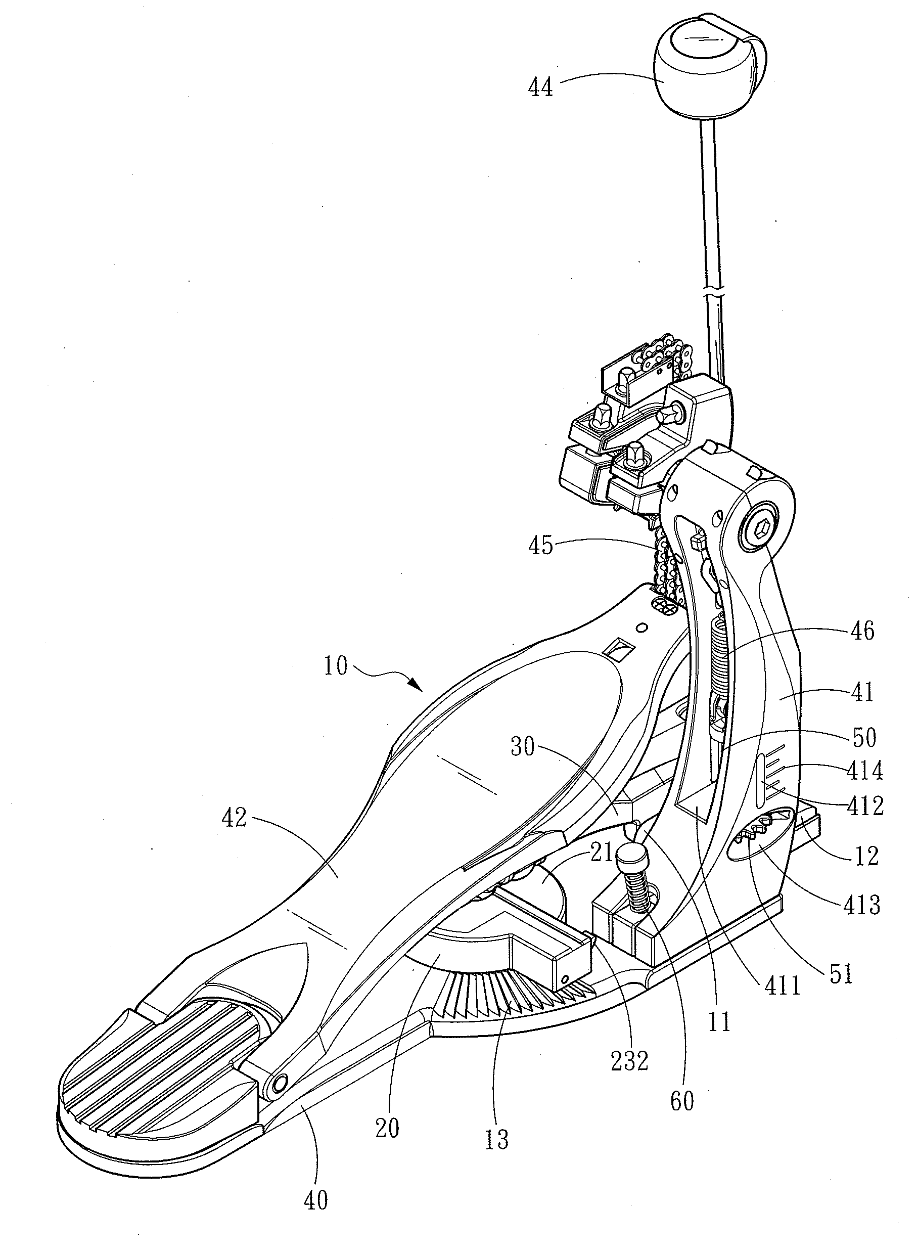
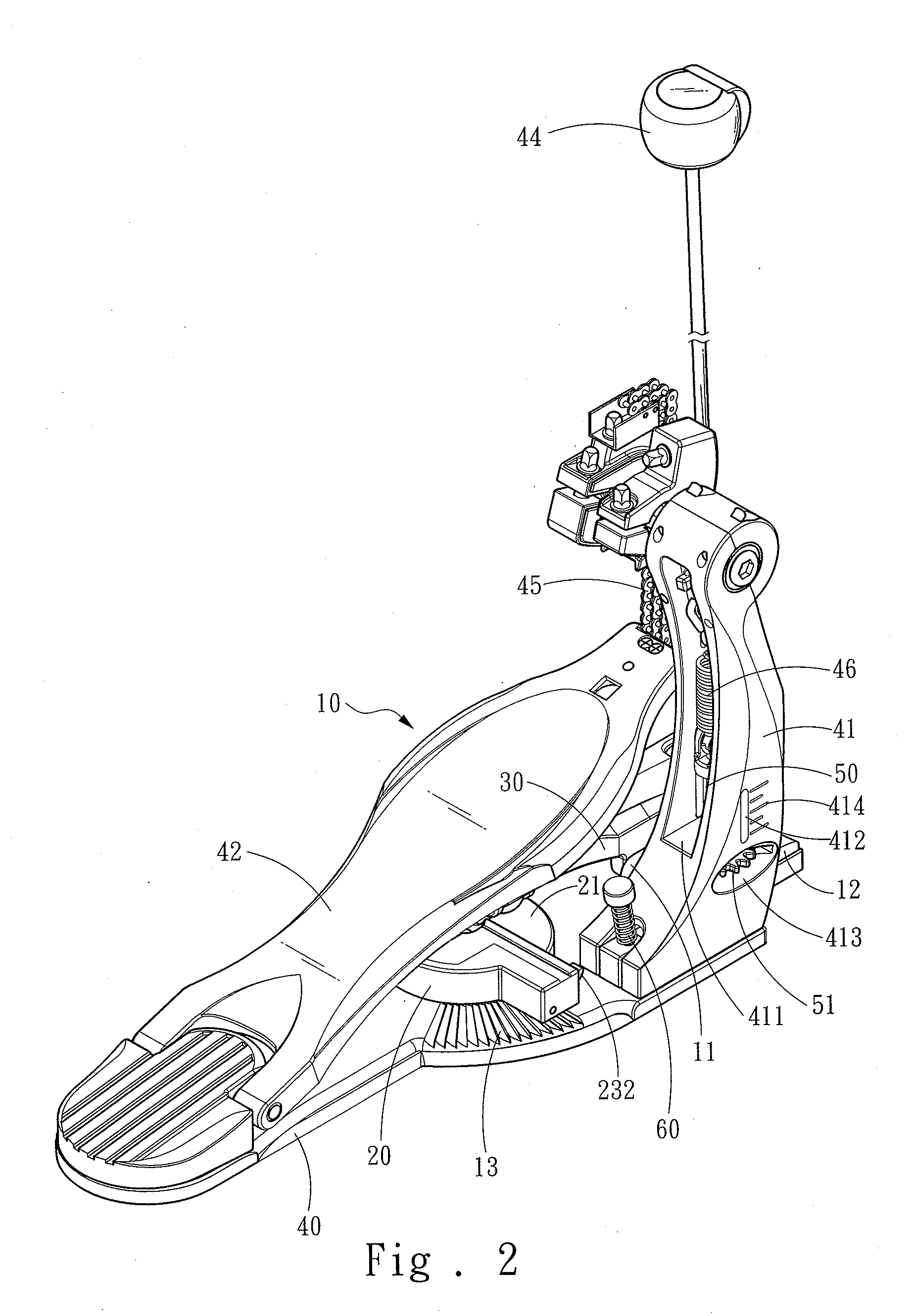
[0014]Please refer to FIGS. 2, 3 and 4, the present invention aims to provide a pedal beating apparatus for musical instruments. It comprises a pedal beating holder 10, an elevation adjustment tray 20 and a clamp beam 30. The pedal beating holder 10 has a fulcrum member 11. The elevation adjustment tray 20 is movable against the pedal beating holder 10 and includes an elevation difference curved surface 21. The clamp beam 30 is hinged on the fulcrum member 11 and includes a clamp end 31 and a leaning end 32 at two ends thereof. The leaning end 32 may have a leaning roller 321 located thereon. A compression spring 33 is interposed between the clamp beam 30 and the pedal beating holder 10 and located between the clamp end 31 and the fulcrum member 11 to allow the leaning end 32 to move downwards to contact the elevation difference curved surface 21. The pedal beating holder 10 further includes a clamp boss 12 facing the clamp end 31.

[0015]The elevation adjustment tray 20 is hinged on ...


PUM


Abstract

A pedal beating apparatus for musical instruments comprises a pedal beating holder, an elevation adjustment tray and a clamp beam. The elevation adjustment tray is movable against the pedal beating holder and has an elevation difference curved surface. The pedal beating holder has a fulcrum member. The clamp beam hinged on the fulcrum member has a clamp end and a leaning end at two ends. A compression spring is interposed between the clamp beam and pedal beating holder and located between the clamp end and fulcrum member to allow the leaning end to move downward to contact the elevation difference curved surface. By moving the elevation adjustment tray, position of the leaning end contacting the elevation difference curved surface is adjusted to further drive the clamp end to move. Thus distance between the clamp end and clamp boss can be changed to rapidly clamp drum hoops with varying thicknesses.

Description

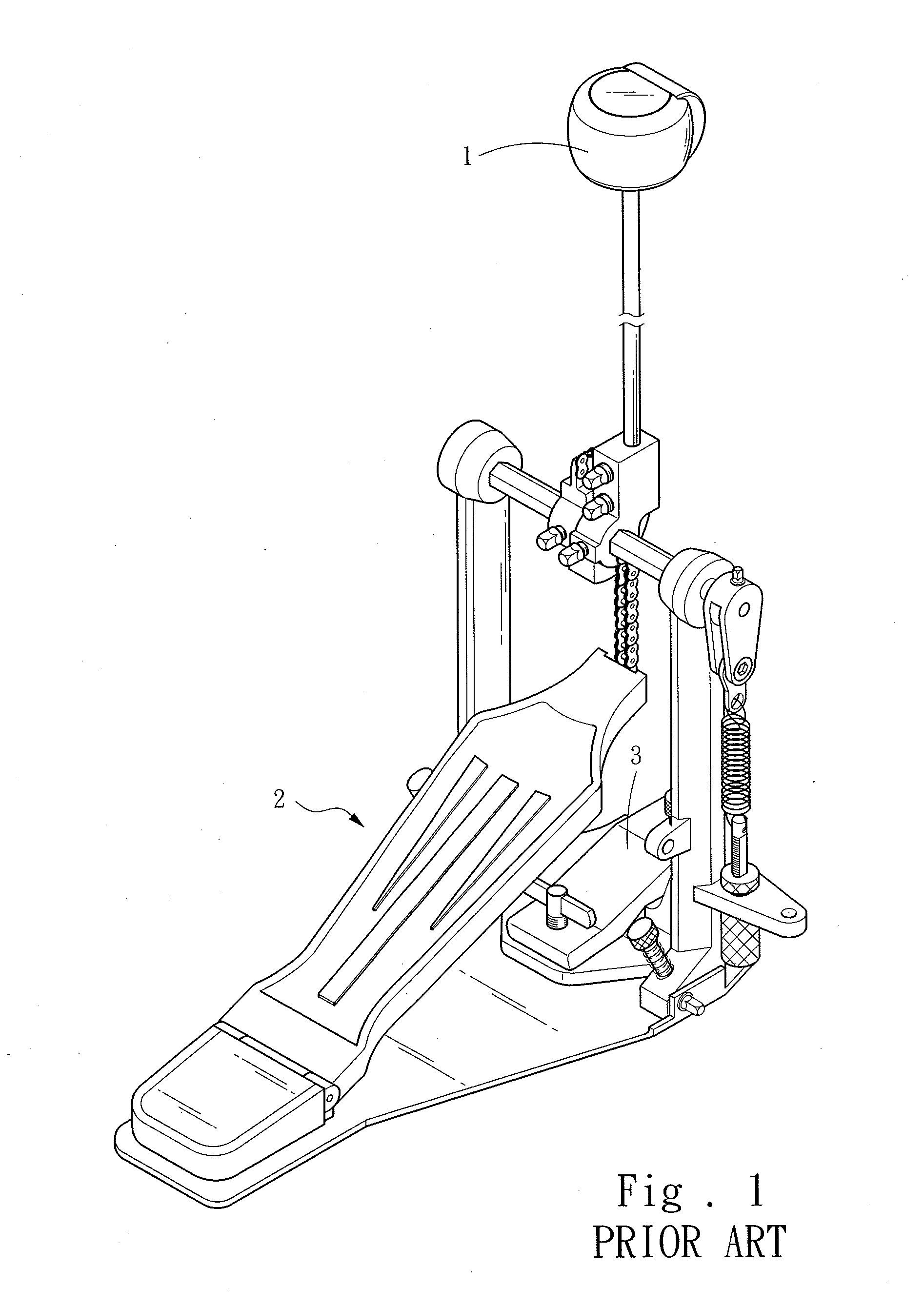
FIELD OF THE INVENTION[0001]The present invention relates to a pedal beating apparatus for musical instruments and particularly to a pedal beating apparatus for drums with different drum hoops.BACKGROUND OF THE INVENTION[0002]A beater aims to beat a drum to generate sound that determines the rhythm of music, which plays an important role in a music band. The timbre generated by beating a drum via the beater mainly is determined by the characteristics of the drum. Different drums have different timbres. Performers can change the drums according to their preferences and musical requirements during performance.[0003]Referring to FIG. 1, a conventional beater 1 generally is installed on a pedal beating holder 2 controlled by a drummer's foot to get desired rhythm. To present different movement characteristics, the drums with different specifications and weights could be used. In order to fasten the drum hoop (not shown in the drawing) of a drum to the pedal beating holder 2, the convent...

Claims


Application Information

Patent Timeline
Patent Type & Authority Applications(United States)
IPC IPC(8): G10D13/00
CPCG10D13/006G10D13/11
Inventor LIAO, TSUN-CHI
Owner LIAO TSUN CHI
Learn More