
Pipeline Network Optimization Using Risk Based Well Production

a technology of pipeline network and risk, applied in the direction of stochastic cad, instruments, borehole/well accessories, etc., can solve the problems of hammering the efficiency of wells, unable to take into account the entire pipeline architecture, and failing to optimize the complete pipeline architecture for better resource utilization, etc., to achieve the effect of projecting costs more accurately

Inactive Publication Date: 2014-06-19
FLUOR TECH CORP
View PDF2 Cites 25 Cited by
  • Summary
  • Abstract
  • Description
  • Claims
  • Application Information

AI Technical Summary

Benefits of technology

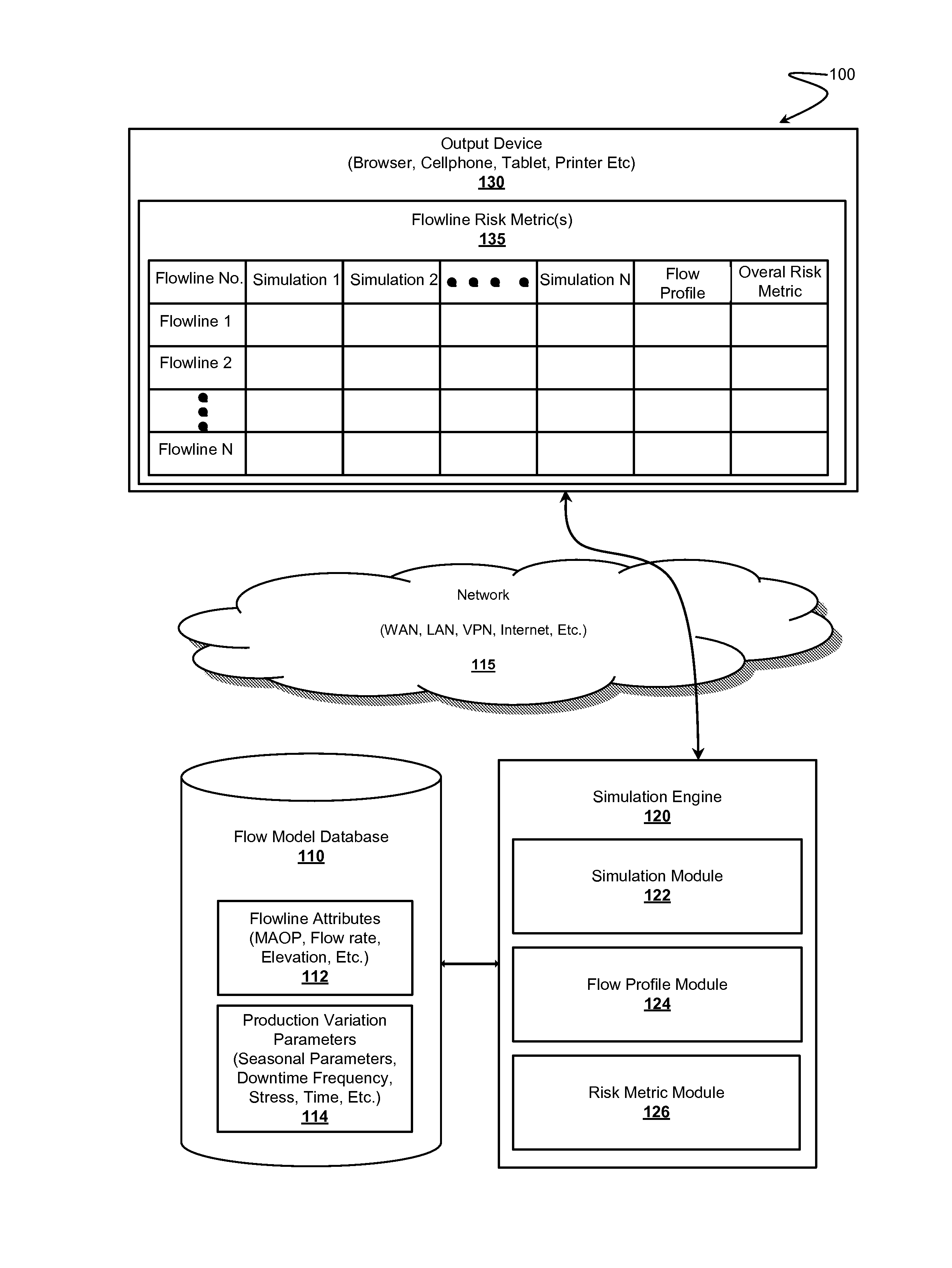
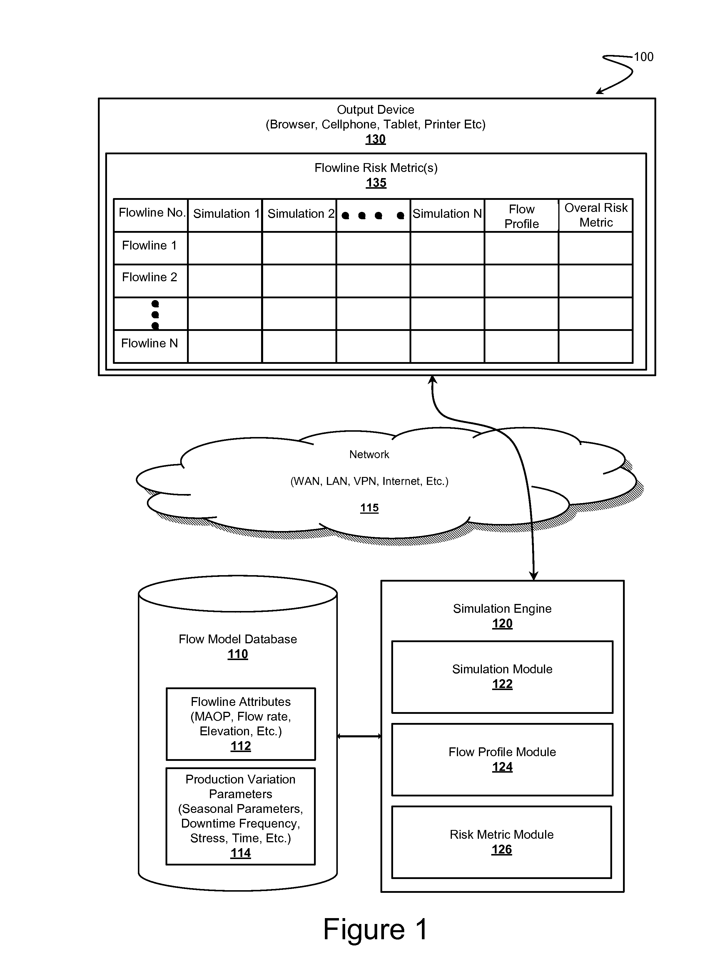
The patent is for a system that can virtualize a network of pipes and determine the likelihood of each flowline being able to handle the expected flow of oil or gas. This helps to identify areas of potential risk and take appropriate measures to control the operation of the flowline. The system can also measure the cost of different options and help control future costs more accurately. Overall, the technology improves the efficiency and safety of oil and gas piping systems.

Problems solved by technology

Similarly, change in flowline structure, performance, or functionality, can hamper the efficiency of the wells and hamper their actual production.
Furthermore, Rashid focuses specifically on gas lift technologies and not on general pipeline network structures.
The above disclosed materials merely disclose optimization of wells and are directed to improving the production output from the wells by using or more modeling techniques but fail to take into consideration the entire pipeline architecture to optimize the complete architecture for better utilization of resources.

Method used


Image

  • Pipeline Network Optimization Using Risk Based Well Production
  • Pipeline Network Optimization Using Risk Based Well Production
  • Pipeline Network Optimization Using Risk Based Well Production

Examples


Embodiment Construction

[0021]It should be noted that while the following description is drawn to pipeline network optimization systems and methods, various alternative configurations are also deemed suitable and may employ various computing devices including servers, interfaces, systems, databases, agents, peers, engines, controllers, or other types of computing devices operating individually or collectively. One should appreciate the computing devices comprise a processor configured to execute software instructions stored on a tangible, non-transitory computer readable storage medium (e.g., hard drive, solid state drive, RAM, flash, ROM, etc.). The software instructions preferably configure the computing device to provide the roles, responsibilities, or other functionality as discussed below with respect to the disclosed system. In especially preferred embodiments, the various servers, systems, databases, or interfaces exchange data using standardized protocols or algorithms, possibly based on HTTP, HTTP...


PUM


Abstract

Systems and methods for pipeline network optimization are presented. The pipeline network can be represented through a flow model, which can include a plurality of modeled wells operatively coupled to production facilities through one or more flowlines. Risk profiles of the one or more flowlines can be determined based on flowline attributes of each flowline and based on a simulation of the flow model that uses production variation in wells connected to the respective flowline as a parameter to generate flow profile of the flowline. Understanding the risk profile of each flowline through a risk metric can help assess the production potential of each flowline and wells associated thereto and optimize the network cost of operation or maintenance.

Description

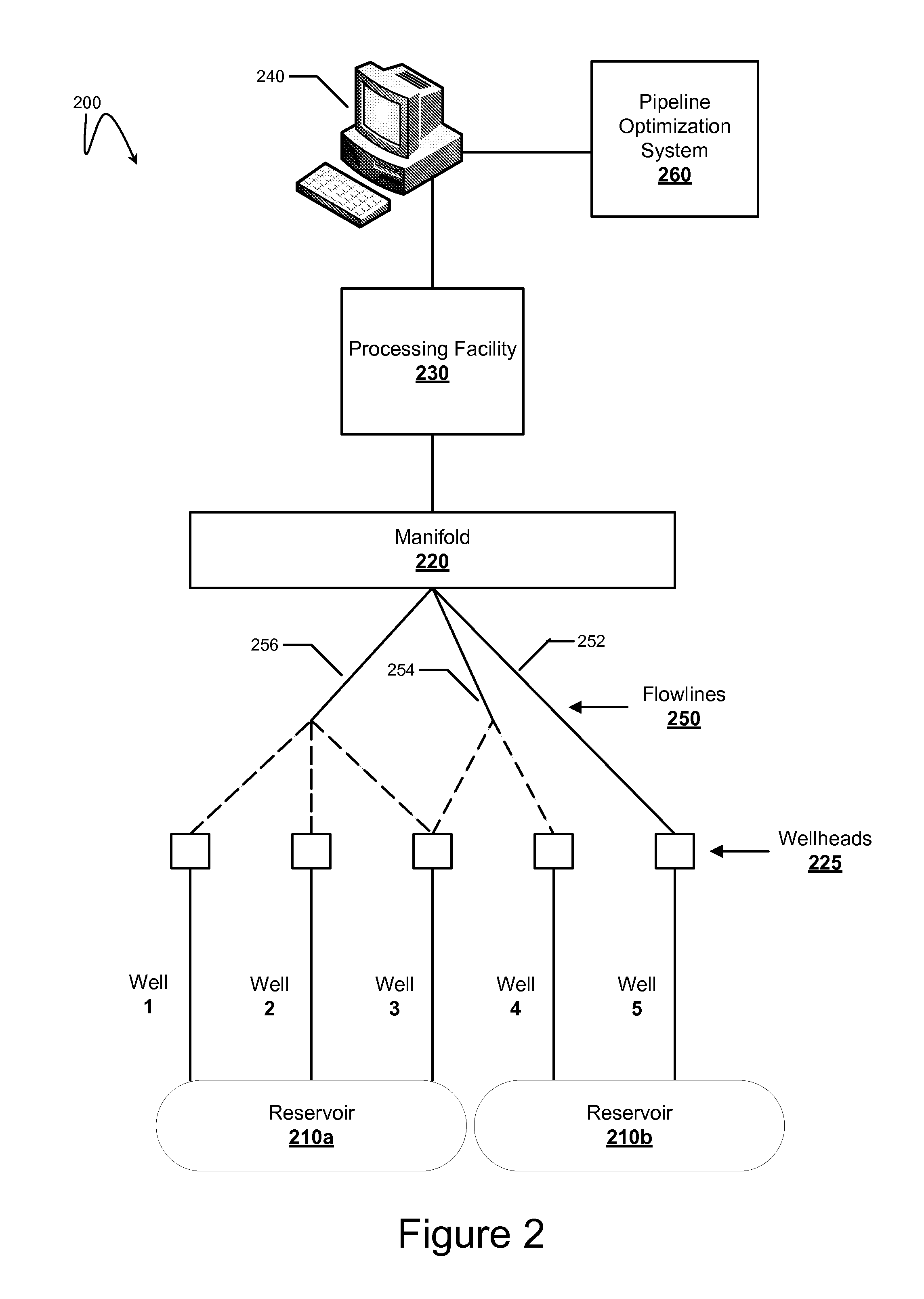
FIELD OF THE INVENTION[0001]The field of the invention is pipeline network optimization technologies.BACKGROUND[0002]Pipeline networks are typically used in transportation of various materials such as hydrocarbons, oil, CO2, LPG, liquids, wet gas, LNG, or other products, and involve extensive engineering by connecting one or more wells having such materials to subsea production or processing facilities through one or more flowlines. Flowlines, which are commonly also referred to as pipelines, are used for carrying the material at varying pressures or temperatures. Pipeline networks follow multiple structures and interconnectivity patterns, wherein for instance, one network can have a single well connected to multiple flowlines, wherein another network can have multiple wells connected with multiple flowlines or even a single flowline. In complex network architectures, multiple flowlines take input from multiple wells and therefore performance of each well can impact the flow of mate...

Claims


Application Information

Patent Timeline
Patent Type & Authority Applications(United States)
IPC IPC(8): G06F17/50
CPCG06F17/5009F17D1/04F17D5/00F17D3/01F17D1/08G06F2111/08G06F2113/14G06F30/18G06F30/20E21B43/00G06F2113/08G06F30/25
Inventor ANDREWS, PAUL I.LIVERMORE, JOHNGARLICK, PAULPARKASH, SUB
Owner FLUOR TECH CORP
Learn More