
Separator

a technology of separator and filter, which is applied in the field of separator, can solve the problem of not reaching significant results, and achieve the effect of improving the efficiency of the crankcase ventilation system and high efficiency

Active Publication Date: 2014-06-19
PARKER HANNIFIN MFG LTD
View PDF3 Cites 34 Cited by
  • Summary
  • Abstract
  • Description
  • Claims
  • Application Information

AI Technical Summary

Benefits of technology

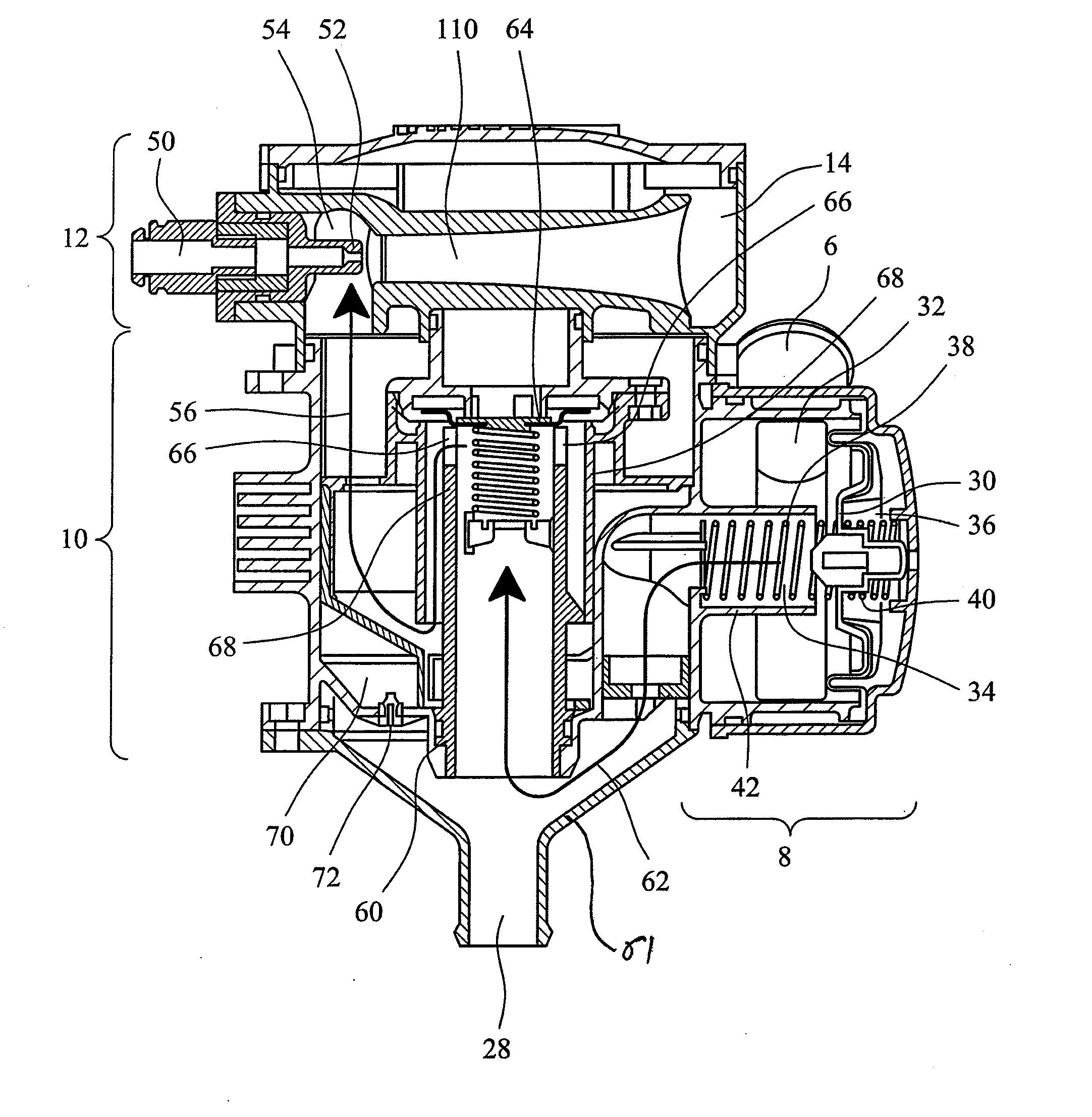
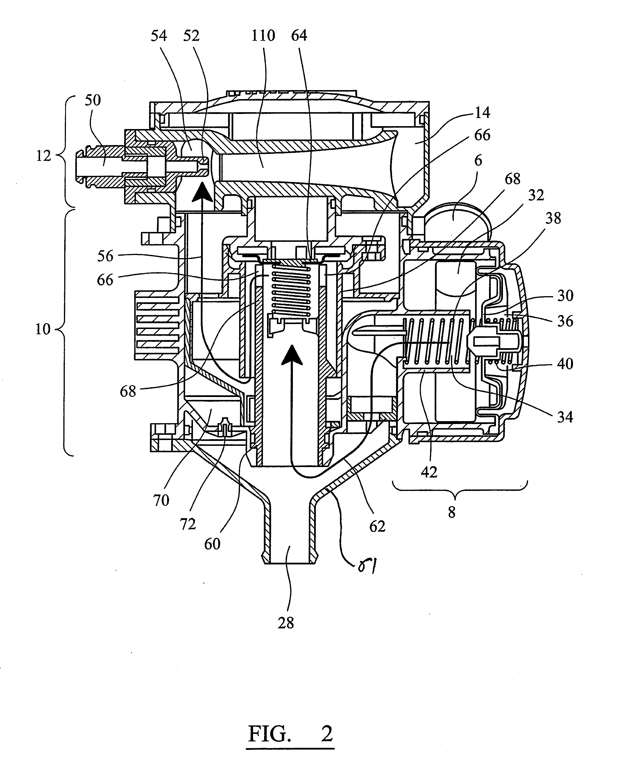
The present invention aims to improve the efficiency of crankcase ventilation systems, especially for closed crankcase ventilation systems (CCV systems). The invention provides a high efficiency separator that prevents inlet pressure from rising to unacceptable levels. By dividing the available pressure drop provided by the pump across multiple separation stages, the invention achieves significantly higher rates of gravimetric and fractional separation efficiency compared to a single stage separator utilizing the same pressure drop. The invention maximizes the separation efficiency while providing effective pressure regulation across the separator to prevent the crankcase pressure falling below or exceeding predetermined limits. The invention also controls the open area of the aperture according to the available pump pressure, reducing or eliminating the effect of pump surge and high and low pressure hunting which commonly occur with unregulated or poorly regulated pumped separators.

Problems solved by technology

This significant result is not achievable without the benefit of an external energy source in the form of a pump.

Method used


Image

  • Separator
  • Separator
  • Separator

Examples


first embodiment

[0094]Referring to FIG. 8, this illustrates a separator in accordance with the invention. The separator comprises a cyclonic pre-filter 200, a first variable impactor separation stage 202 and an eductor pump 204 each of which is generally the same as the cyclonic pre-filter 61, separator 10 and jet pump 12 of FIG. 5 and so will not be fully described again here. However, differing from the separator of FIG. 5, between the first variable impactor separation stage 202 and the jet pump 204 is a second variable impactor separation stage 206. The second variable impactor separation stage 206 which is generally the same as the first variable impactor separation stage 202, however it may be optimised to further increase the overall fractional and gravimetric separation efficiencies by the use of springs having different spring response rates. In particular, the spring response rate for the springs in the second stage 206 may be chosen to allow a portion of the vacuum generated by the jet p...

second embodiment

[0102]Referring to FIG. 9, this illustrates a separator in accordance with the present invention. The separator is generally the same as that shown in FIG. 8 except that the second variable impactor separator stage 206 has been replaced by a filter media separation stage 218. This combination of inertial impaction within the variable impactor separator 202 (and also within the cyclonic pre-filter if present) followed by fibrous depth filtration has shown to provide exceedingly high fractional and gravimetric efficiencies. In particular, certain types of known filter media are particularly suitable for filtering very small particle contaminants. As the filter media is not clogged by larger particles due to the action of the variable impactor separator, the filter media is better able to retain this ability to filter very small particles. Additionally, unlike certain conventional filters in which a filter media is provided on its own and must be regularly replaced, because the variabl...


PUM

PropertyMeasurementUnit
Pressureaaaaaaaaaa
Flexibilityaaaaaaaaaa

Abstract

A separator has a first inlet arranged to receive a fluid stream, and first and second separation stages coupled together in series; A pump coupled to the second separation stage generates an area of reduced pressure to draw the fluid stream through the first and second separation stages. One of the stages includes a variable impactor separator comprising a first chamber arranged to receive the fluid stream, and a second chamber coupled to the first chamber through an aperture to accelerate the first fluid stream. The stream is incident upon an impaction surface to separate contaminants from the fluid stream. An actuator adjusts the open area of the aperture according to a pressure differential between fluid pressure in the first chamber and a reference fluid pressure in a third chamber. The other of the separation stages is a second variable impactor separator or a filter media.

Description

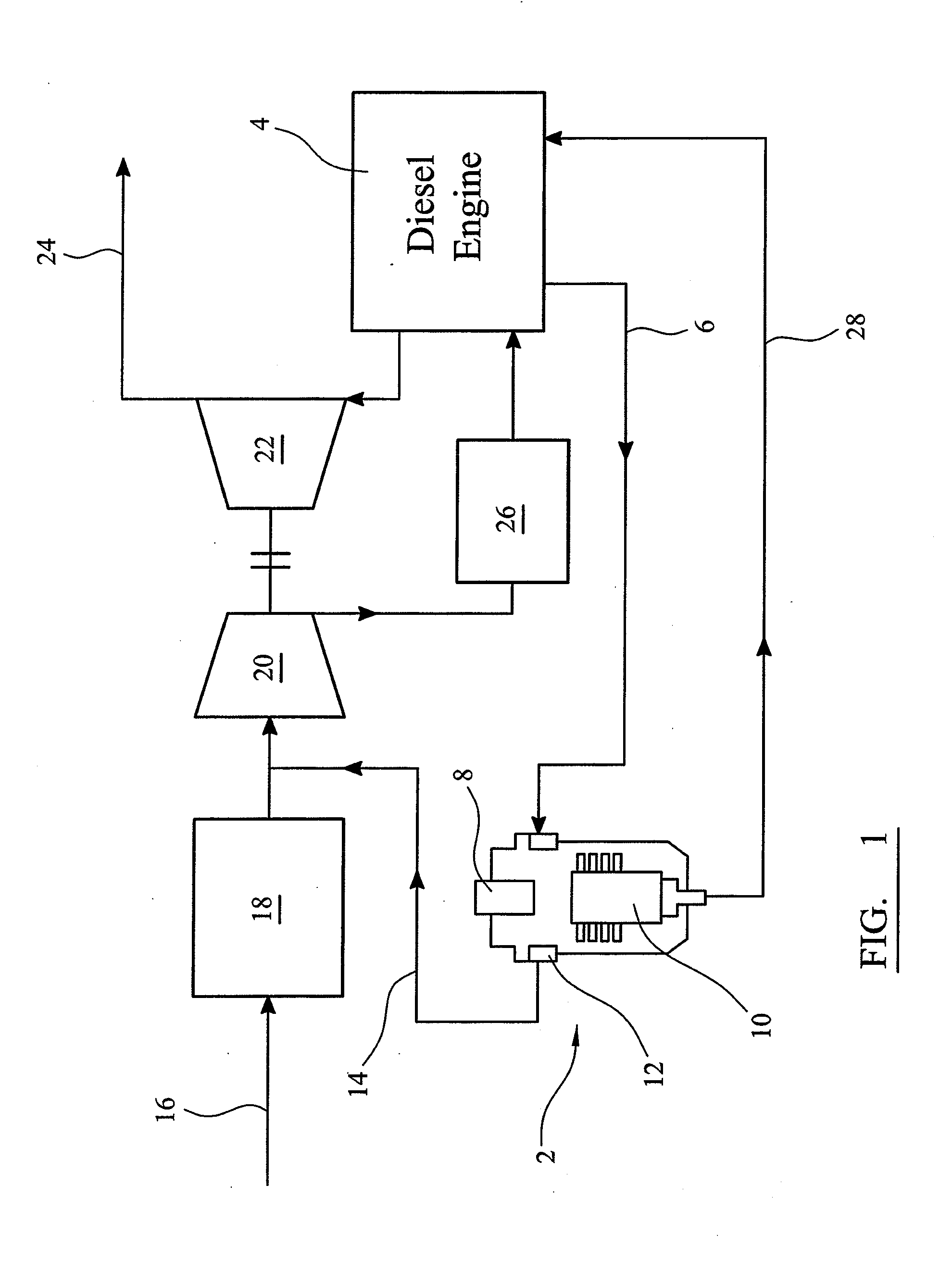
CROSS REFERENCE TO RELATED APPLICATIONS[0001]The within application is a continuation of International Application No. PCT / GB2012 / 051729, filed Jul. 19, 2012, and which designated the United States; and which claims priority to Great Britain Application No. 113072.1, filed Jul. 29, 2011, the disclosures of which are expressly incorporated herein by reference.BACKGROUND OF THE INVENTION[0002]The present invention relates to a separator. In particular, the present invention relates to a separator for separating particulate, liquid and aerosol contaminants from a fluid stream. Certain embodiments of the present invention relate to a separator for separating particulate, liquid and aerosol contaminants from a blow-by gas stream within a reciprocating engine. Separators in accordance with particular embodiments of the present invention incorporate mechanisms for regulating the pressure within a crankcase ventilation system. Embodiments of the present invention provide a pump assisted int...

Claims


Application Information

Patent Timeline
IPC IPC(8): F01M13/04F02M35/022
CPCF01M13/04F02M35/0226F02M35/0223B01D45/08F01M2013/0016F01M2013/0072F01M2013/026F01M2013/0433F01M2013/0438F02M25/06B01D50/20B01D45/16B01D46/0031B01D45/04B01D45/12B04C7/00F01N3/037F01M2013/0427
Inventor COPLEY, DANIELMINCHER, ADRIAN
Owner PARKER HANNIFIN MFG LTD
Learn More