Endless circulation path for linear rail

Active Publication Date: 2014-06-12
CHIEFTECH PRECISION
View PDF3 Cites 4 Cited by
  • Summary
  • Abstract
  • Description
  • Claims
  • Application Information

AI Technical Summary

Benefits of technology

The present invention provides a smooth and efficient contact between a retainer and a rail by guiding the retainer in a load path using smoothly connected grooves. The angle between the retainer and the trangential faces on the ends of the contact face can be small to avoid the retainer from hitting the rail, and the guide paths reduce the stress on the retainer, resulting in a longer life of use. This invention allows for a smooth and smooth movement of the retainer in various directions.

Problems solved by technology

However, the above-mentioned arrangement generates an angle between the endless circulation path and the horizontal plane, and increases the height of the sliding base.
However, the above-mentioned arrangement makes one end of the retainer to be too close to the rail and the retainer may drop and hit the rail.

Method used


Image

  • Endless circulation path for linear rail
  • Endless circulation path for linear rail
  • Endless circulation path for linear rail

Examples


Embodiment Construction

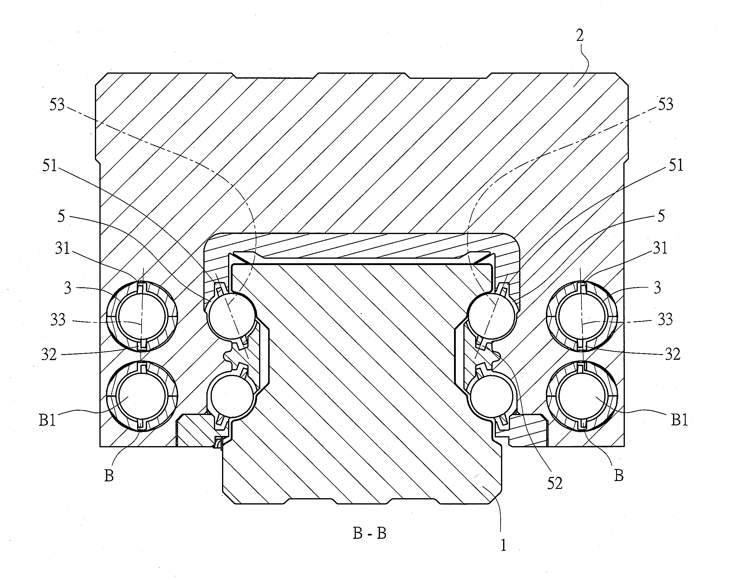
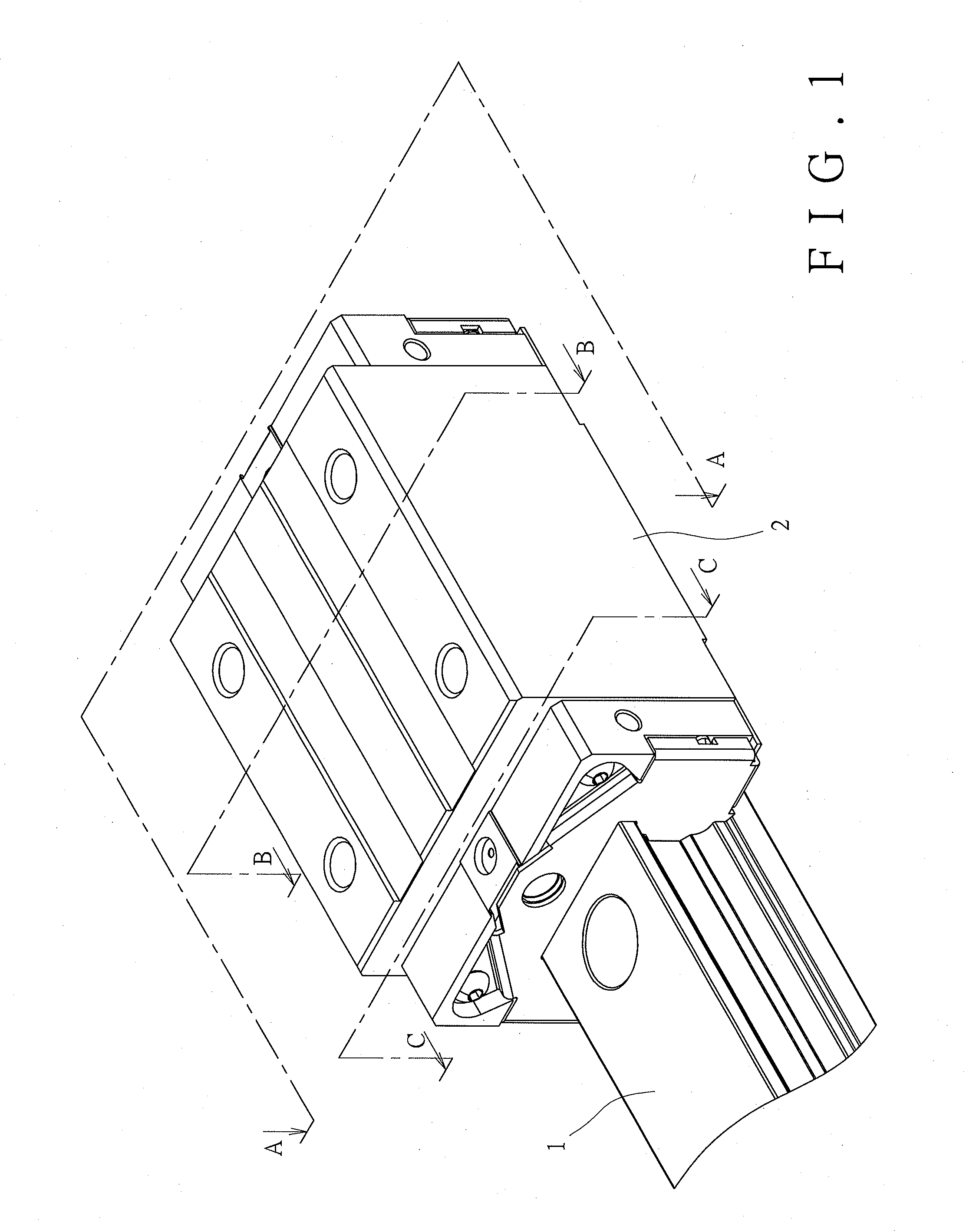
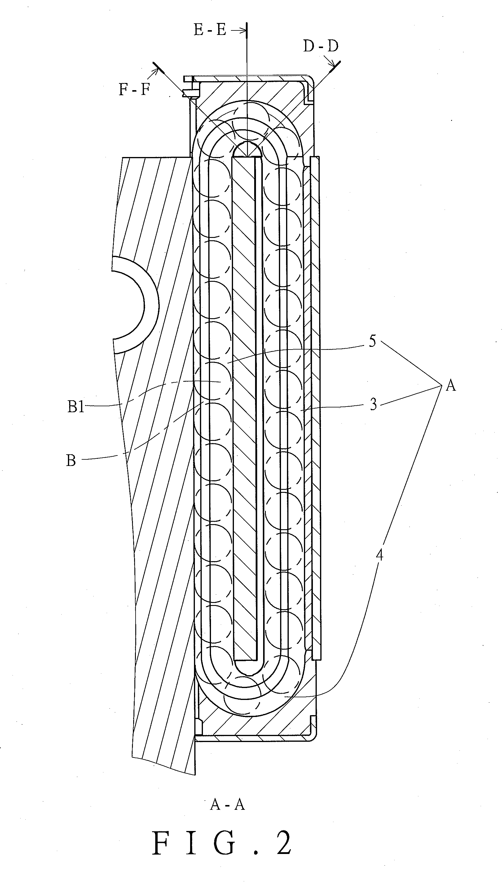
[0022]Referring to FIGS. 1 and 2, the endless circulation path “A” for a linear rail of the present invention comprises a rail 1 and a sliding base 2 which is movable on the rail 1 and the endless circulation path “A” is defined in the sliding base 2. Two direction change paths 4 are respectively formed in two ends of the sliding base 2. A loaded path 5 is defined between the rail 1 and the sliding base 2, and an unloaded path 3 is defined in the sliding base 2. The two direction change paths 4 are connected between the loaded path 5 and the unloaded path 3 to form the enclosed endless circulation path “A”. The endless circulation path “A” has multiple balls “B1” which are retained in a retainer “B” so that the balls “B1” are positioned at their respective positions. Top grooves 31, 41, 51 and bottom grooves 32, 42, 52 are provided in the endless circulation path “A” so as to guide the retainer “B” to smoothly move in the endless circulation path “A” (FIGS. 3-7). As shown in FIG. 3,...


PUM


Abstract

An endless circulation path for a linear rail includes a loaded path, an unloaded path and two direction change paths which are connected between the loaded path and the unloaded path. Each of the unloaded path, the direction change paths and the loaded path has top and bottom grooves. A first line is connected between top and bottom grooves of the unloaded path. A second line is connected between the top and bottom grooves of each of the direction change paths. A slope of the second line, starting from the intersection between the direction change path and the unloaded path to the intersection between the direction change path and the loaded path, is gradually inclined relative to the first line. A third line is connected between the top and bottom groove of the loaded path. The third line is inclined relative to the first line.

Description

FIELD OF THE INVENTION[0001]The present invention relates to an endless circulation path for a linear rail, and more particularly, to grooves in the endless circulation path to guide the ball retainer.BACKGROUND OF THE INVENTION[0002]The conventional linear track rail refers to a solid sliding base endlessly moving along the rail. There is a loaded path formed between the sliding base and the rail, and the sliding base has an unloaded path. Two direction change paths are formed in two ends of the sliding base so as to be connected between the loaded path and the unloaded path. The two direction change paths, the loaded path and the unloaded path form an endless circulation path, and multiple balls are moved along the endless circulation path to achieve the purpose of the movement of the sliding base.[0003]In order to ensure that the balls are moved along the correct path of the endless circulation path and do not hit each other. A ball retainer is used to separate each of the balls....

Claims


Application Information

Patent Timeline
IPC IPC(8): F16C29/06
CPCF16C29/0609F16C29/0645F16C29/06
Inventor HSU, MING-CHE
Owner CHIEFTECH PRECISION
Why Eureka
Try Eureka