Roller bearing

Inactive Publication Date: 2011-10-20
COOPER ROLLER BEARINGS
View PDF9 Cites 15 Cited by
  • Summary
  • Abstract
  • Description
  • Claims
  • Application Information

AI Technical Summary

Benefits of technology

In this case the provision of the relief portions allows the tapered rollers to pass smoothly over the joints between the semicircular parts of the inner ring and inner tapered race.
In this way the arcuate distance between the opposite ends of an end surface is reduced.

Problems solved by technology

To improve the smooth passage of the roller over the joints, one embodiment provides the angle of the end surfaces of the semicircular parts of the inner tapered race to be at as large an angle as possible with respect to the bearing axis but this is particularly difficult with the inner ring and inner race because the width of the component makes the arcuate distance between the opposite ends of an end surface to be too large and hence makes it difficult to remove the two semicircular parts to service the bearing.

Method used


Image

  • Roller bearing
  • Roller bearing
  • Roller bearing

Examples


Embodiment Construction

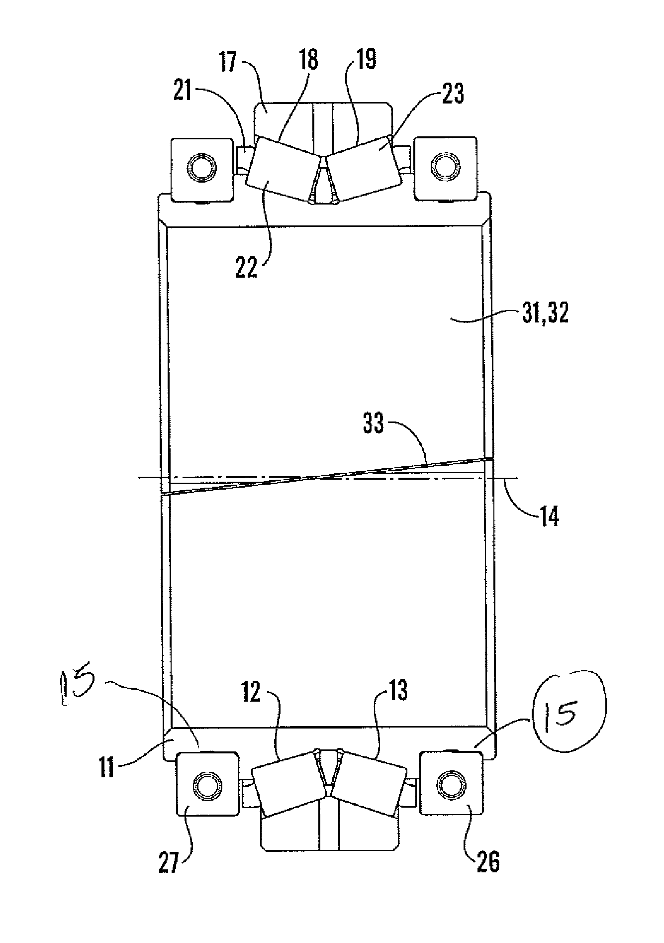
Referring to FIG. 1, there is shown a taper roller bearing in accordance with the invention. An inner ring 11 includes two races or raceways 12, 13 which each include bearing surfaces 35. The two raceways 12, 13, are set in a back-to-back format that is they are set at opposite angles to the axis 14 of the bearing i.e. they have opposite tapers.

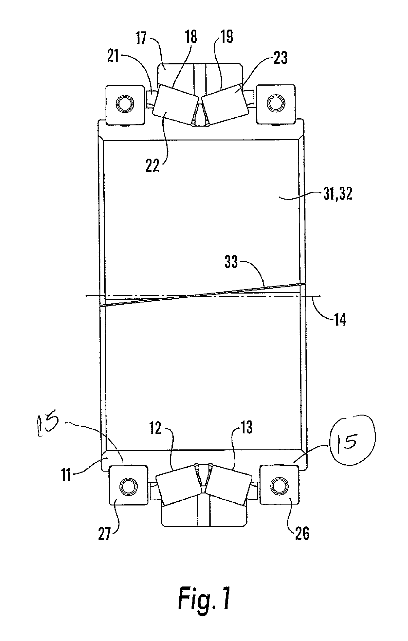
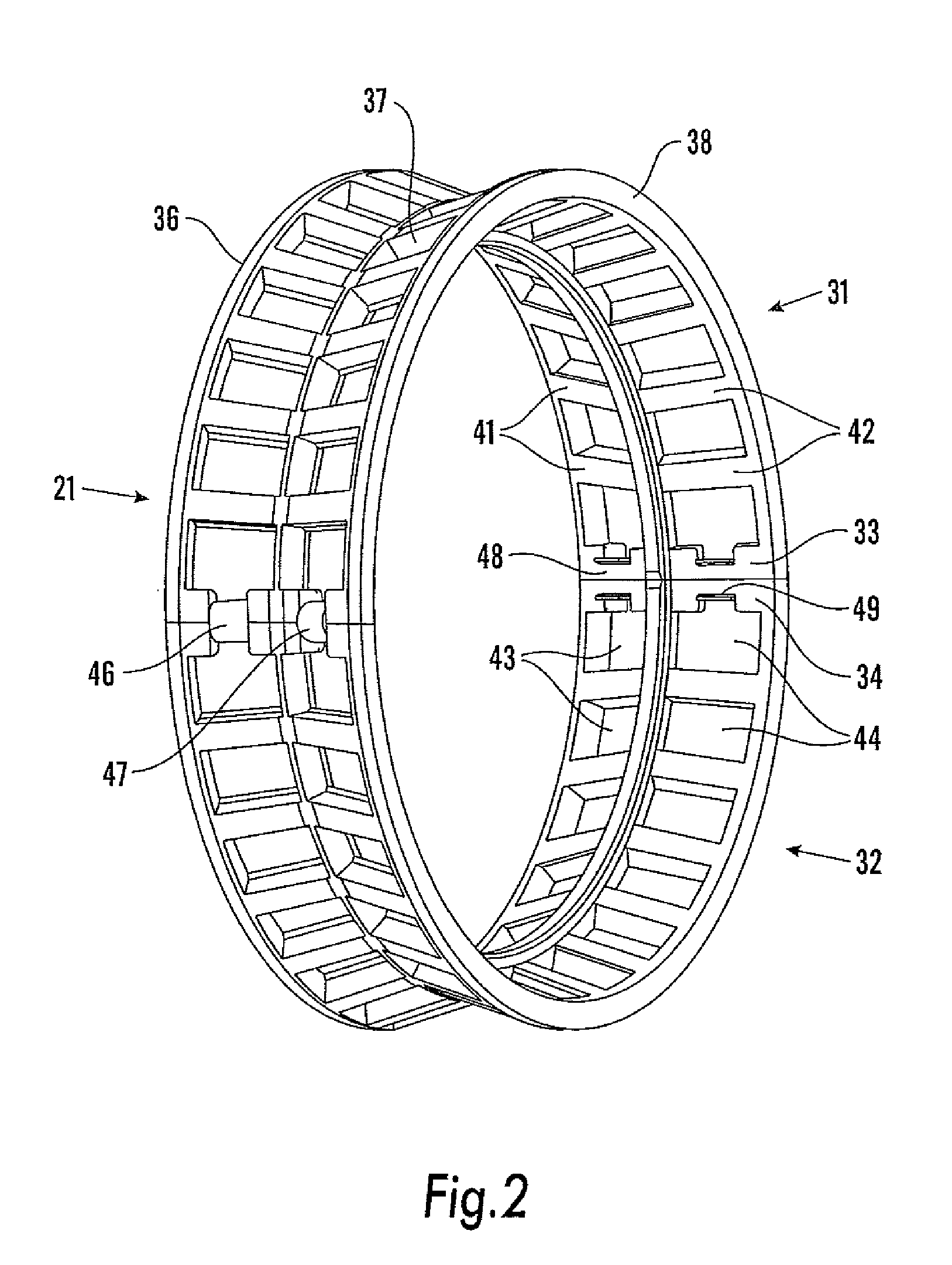
There is furthermore provided an outer ring 17 with two races or raceways 18, 19 at similar (but not identical as will be clear later) opposite angles to the axis 14 to the raceways 12, 13. Mounted between the inner 11 and outer 17 rings is a circular cage 21 (illustrated in more detail in FIG. 2), the cage mounting two side by side rows of rollers 22, 23, rollers 22 being mounted between raceways 12 and 18, and rollers 23 being mounted between raceways 13 and 19. The rollers are slightly conical. The apices of the cones of the raceways 12 and 18 and rollers 23 are common and lie on the bearing centre line, and the apices of the cones of the ...


PUM


Abstract

A split roller bearing comprising an inner ring including an inner race, an outer ring including an outer race, a cage mounted between the inner and outer races, said cage mounting t rollers which engage the inner and outer races, said inner ring and inner race, outer ring and outer race, and cage each comprising two substantially semicircular parts, the relevant semicircular parts being mounted end-to-end to provide a circular component, whereby the two semicircular parts of the inner ring and inner tapered race, outer ring and outer race, and cage, may be separated from one another to allow the roller bearing to be dismantled when worn without removal of the component supported by the bearing.

Description

BACKGROUNDCylindrical roller bearings generally comprise an inner ring which includes an outwardly facing raceway or bearing surface, an outer ring which includes an inner facing raceway, and mounted between them, a row of rollers which engage the two raceways, the rollers being mounted in a cage.In a cylindrical roller bearing thrust loads are carried between the ends of the rollers and adjacent faces of roller guide lips. This is a sliding contact which is difficult to lubricate and thus the thrust load carrying capacity is relatively low compared to other bearing types, particularly at high shaft speeds.One bearing type that is able to support high thrust loads is the taper roller bearing. In this arrangement, the raceways and rollers have conical surfaces. For a single raceway, the apices of the cones of the raceways and rollers are common and coincide with the bearing centre line.Taper roller bearings are used extensively, particularly in gearboxes and axle boxes. However, one ...

Claims


Application Information

Patent Timeline
IPC IPC(8): F16C19/34F16C19/38F16C43/04
CPCF16C19/38F16C33/48F16C33/504F16C2226/74F16C2240/30F16C2240/34F16C33/60
Inventor CASPALL, MARTIN JANEKMORRIS, STUART CRISPINEARTHROWL, BRIAN EDWARD
Owner COOPER ROLLER BEARINGS
Why Eureka
Try Eureka