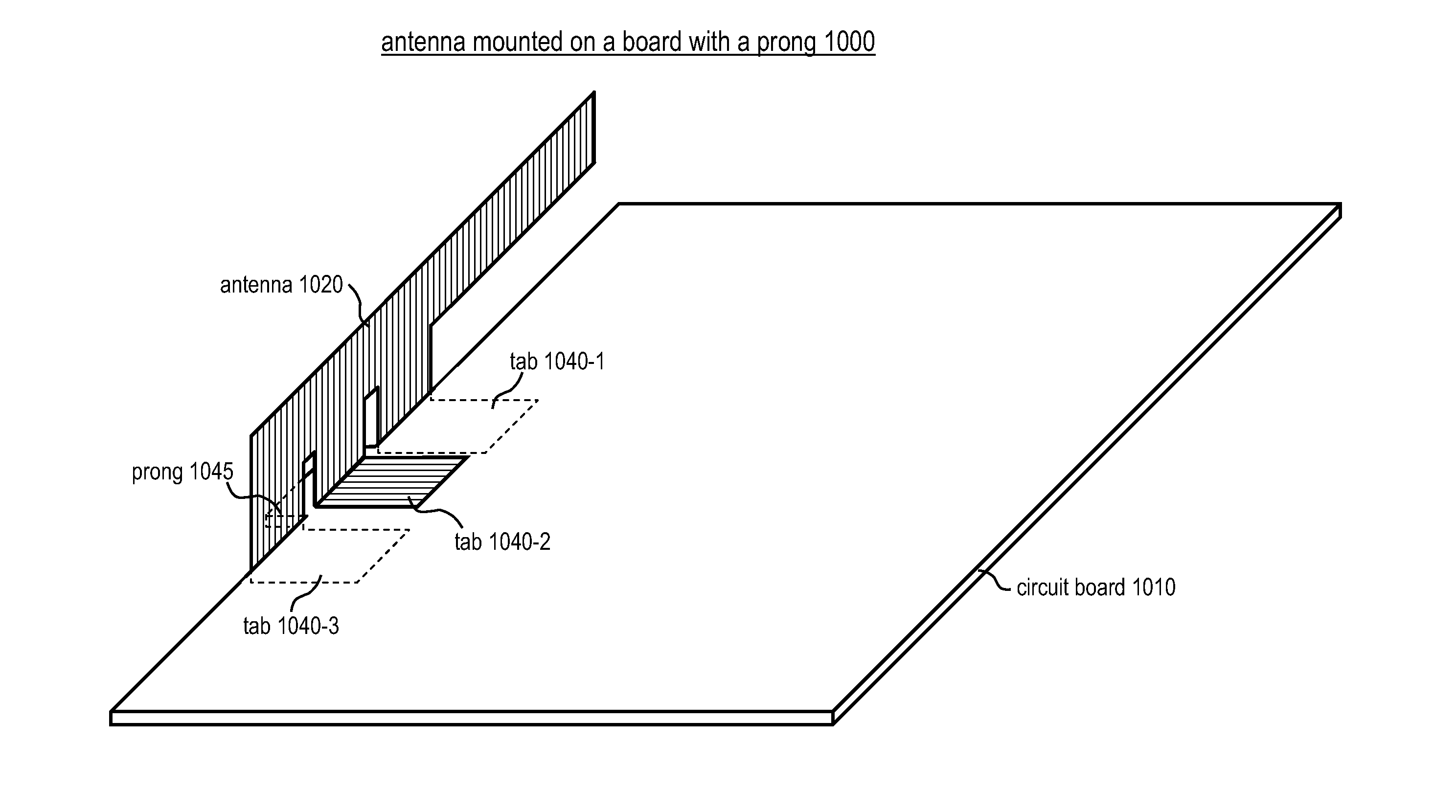
Antenna mounted on a circuit board

a circuit board and antenna technology, applied in the field of radio antennas, can solve the problems of obviating the disadvantages of prior-art antenna mounting methods, and achieve the effect of good antenna performan

Inactive Publication Date: 2014-06-12
OPTICON SENSORS EURO
View PDF0 Cites 15 Cited by
  • Summary
  • Abstract
  • Description
  • Claims
  • Application Information

AI Technical Summary

Benefits of technology

The present invention improves the reliability of electrical contact between a protruding portion that applies pressure and a conductive trace by placing a bump or other protuberance on the protruding portion that applies pressure. The protuberance can have a sharp edge or a barb that further facilitates the reliability of the electrical contact. Additionally, there is a notch in the circuit board, and the antenna is shaped such that some part of it fits in the notch, which helps in correctly mounting the antenna in the correct position. This is also achieved in other embodiments of the present invention by having a prong in the circuit board that fits into a mating part of the antenna designed to accommodate the prong.

Problems solved by technology

By mounting an antenna on an edge of a circuit board, instead of on one of the major surfaces of a circuit board, some of the disadvantages of prior-art methods of antenna mounting are obviated.

Method used


Image

  • Antenna mounted on a circuit board
  • Antenna mounted on a circuit board
  • Antenna mounted on a circuit board

Examples


Embodiment Construction

[0048]This disclosure uses words such as “up”, “down”, “over”, “under”, “top”, “bottom”, “above”, “below” and other such words that, commonly, identify a position or direction in a gravity field. For example, a side of a circuit board depicted in a figure might be identified as the “bottom side”. Such words are used because they make it easier to explain and visualize geometric structures. In particular, objects depicted in figures appear to the observer as having a well-defined orientation relative to gravity, so that identifying a side of a circuit board in a figure as the “bottom side” is an unambiguous identification as it refers to the side of the board that appears to be lower, as depicted. These words are not intended to convey any association with the force of gravity. The present invention does not rely on gravity or on any definitions of such words relative to a gravity field. Embodiments of the present invention operate as intended regardless of the orientation of the emb...


PUM

PropertyMeasurementUnit
electrically conductiveaaaaaaaaaa
pressureaaaaaaaaaa
electromagnetic propertiesaaaaaaaaaa

Abstract

An electronic circuit that needs to transmit or receive radio waves achieves that goal by using an antenna. This disclosure teaches an antenna that can be mounted on an edge of a circuit board. This disclosure teaches antenna shapes that, when mounted on an edge of a circuit board, can advantageously make contact with circuits on both sides of the board. Some antenna shapes have protruding portions with springiness that facilitates affixing the antenna to the board and facilitates reliable electrical contacts with the circuits. The disclosure also teaches methods for mounting an antenna on an edge of a circuit board.

Description

FIELD OF THE INVENTION[0001]moon The present invention relates to radio antennas in general, and, more particularly, to antennas mounted on circuit boards.BACKGROUND OF THE INVENTION[0002]There is a desire to have wireless devices that are small and low-cost. Wireless communication in wireless devices is most commonly accomplished through radio waves that are transmitted and received by means of an antenna. Therefore, the antenna is an important component of most wireless devices, especially because its size is largely determined by the wavelength of the desired radio waves. With the continuing trend in wireless devices toward smaller and smaller size, designing the antenna has become a notoriously difficult task that, in practice, is accomplished with limited success in achieving effective antenna performance.[0003]The effectiveness of an antenna depends on attributes such as, for example, and without limitation, the shape of the antenna, its placement relative to other components ...

Claims


Application Information

Patent Timeline
Patent Type & Authority Applications(United States)
IPC IPC(8): H01Q1/22H01P11/00
CPCH01P11/00H01Q1/22H01Q1/088H01Q1/38H01Q9/0421H05K3/303H05K3/3415H05K2201/0311H05K2201/10098H05K2201/10265H05K2201/10568H05K2201/10621Y10T29/49016Y10T29/49018Y02P70/50
Inventor AZHARI, ALEXANDER
Owner OPTICON SENSORS EURO
Why Eureka
Try Eureka