
Universal power supply system

a power supply system and universal technology, applied in the field of universal power supply systems, can solve the problems of power supply manufacturers that cannot be easily identified, power supply manufacturers are hardly known, and the damage arising from over-power conditions is inevitabl

Active Publication Date: 2014-06-12
ACBEL POLYTECH INC
View PDF2 Cites 10 Cited by
  • Summary
  • Abstract
  • Description
  • Claims
  • Application Information

AI Technical Summary

Benefits of technology

The present invention provides a universal power supply system that can be used with different board mounted DC power modules or AC / DC power supply devices without needing to redesign the backboard module. The system includes a housing, a backboard module, multiple AC / DC power supply devices, and multiple board mounted DC power modules. The backboard module is mounted to the housing and has multiple DC power and communication interfaces, as well as a monitoring circuit. The monitoring circuit has multiple enable terminals, multiple specification identification terminals, and a specification mapping table that allows it to automatically detect the model number of each power supply device and set its critical current value or power value for over-current protection. This allows the system to automatically monitor if each power supply device exceeds its critical value for over-current protection, even when different types of power supply devices are used. The technical effects of this invention are improved flexibility and efficiency in the design of power supply systems for various applications.

Problems solved by technology

If the 875 W AC / DC power supply device is selected as the master and the critical power value is still 500 W, damage arising from the over-power condition is inevitable.
However, the power wattage or DC power specifications of the modular AC / DC power supply devices and the board mounted DC power modules used by the power supply manufacturers can be hardly identified from the appearance.
As a consequence, the modular power supply system assembled by the power supply manufacturers is thus prone to errors, such as a board mounted DC power module plugged in a wrong DC power I / O port of the backboard module.
Additionally, the modular power supply system currently still replies on a customized backboard module preventing the production efficiency from being effectively increased.

Method used


Image

  • Universal power supply system
  • Universal power supply system
  • Universal power supply system

Examples


first embodiment

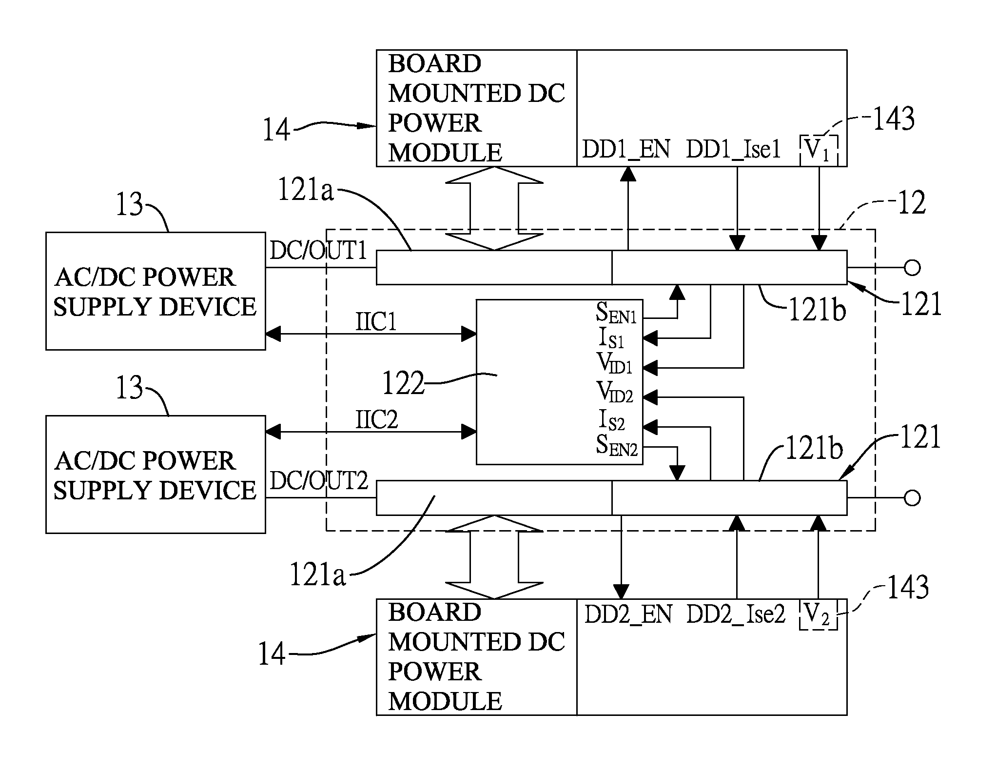
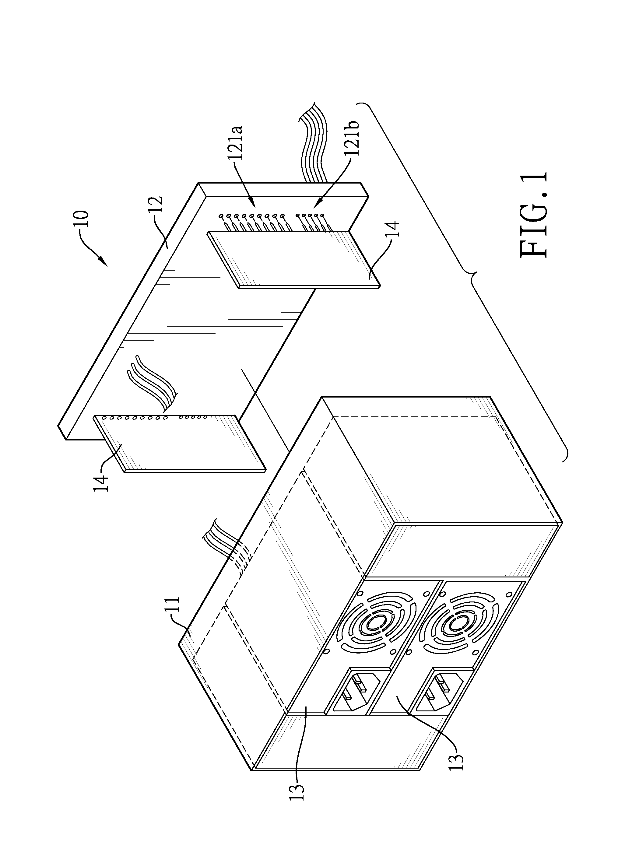
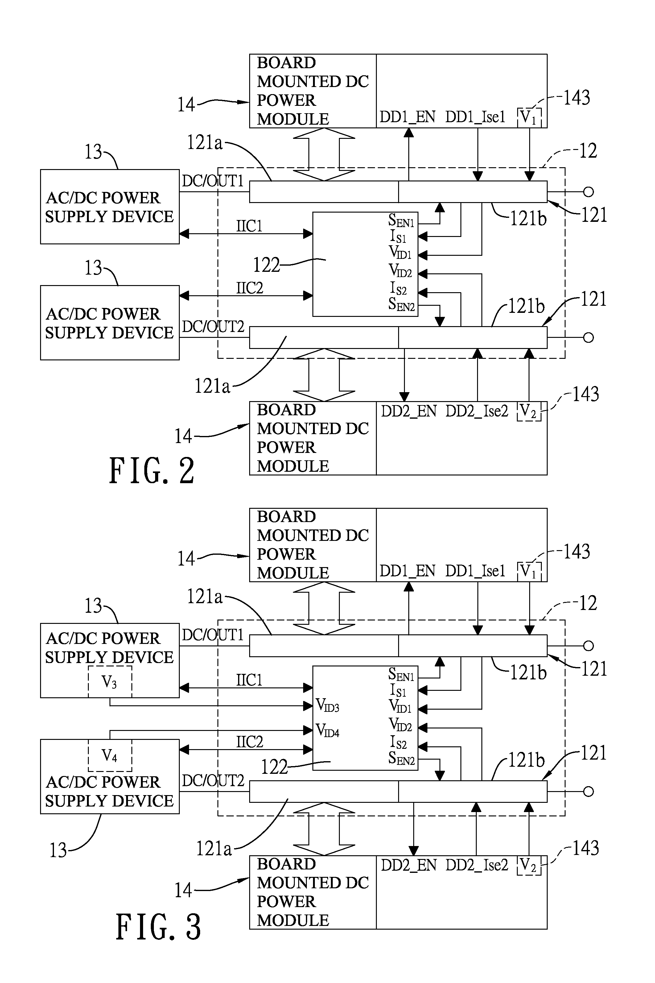
[0047]With reference to FIGS. 1 and 2, a universal power supply system 10 in accordance with the present invention has a housing 11, a backboard module 12, multiple AC / DC power supply devices 13 and at least one board mounted DC power module 14.

[0048]The housing 11 has a first opening and a second opening opposite to each other.

[0049]The backboard module 12 is mounted to the first opening of the housing 11, and has at least one DC power and communication interface 121 and a monitoring circuit 122. Each one of the at least one DC power and communication interface 121 has a DC power I / O port 121a and a communication port 121b. The monitoring circuit 122 is electrically connected to the at least one DC power and communication interface 121 and has at least one enable terminal SEN1, SEN2, at least one current detection terminal IS1, IS2, at least one specification identification terminal VID1, VID2 and a specification mapping table. In the present embodiment, the specification mapping t...

second embodiment

[0055]Similarly, the circuit diagram in FIG. 5 is also applicable to the universal power supply system. The specification mapping table built in the monitoring circuit 122′ further has multiple model numbers corresponding to various AC / DC power supply devices and multiple critical power values corresponding to the model numbers. The specification setting circuit of each AC / DC power supply device 13 is also a voltage divider circuit. By setting an identical reference voltage and selecting a top resistor with a different resistance value, the monitoring circuit 122′ acquires the output voltage specified by each AC / DC power supply device, compares the output voltage with the voltages in the specification mapping table, reads a corresponding critical power value in the specification mapping table, and sets up as the critical power value of the AC / DC power supply device 13 if a matching voltage in the specification mapping table is found. Hence, the critical power value of each AC / DC pow...


PUM


Abstract

A universal power supply system allows each board mounted DC power module or each AC / DC power supply device therein having identical dimensions and appearance to further have a specification setting circuit. When the board mounted DC power module or the AC / DC power supply device is plugged in a backboard module, the specification setting terminal outputs a specification identification signal to a monitoring circuit of the backboard module. As built in with a specification mapping table, the monitoring circuit can compare the specification identification signal to find a model number corresponding to the signal, and automatically sets a critical current value or critical power value of each board mounted DC power module for over-current protection or over-power protection. Accordingly, the universal power supply system can be adapted to different board mounted DC power modules or AC / DC power supply devices without redesigning the backboard module.

Description

BACKGROUND OF THE INVENTION[0001]1. Field of the Invention[0002]The present invention relates to a universal power supply system and more particularly to a power supply system for industrial computers or servers.[0003]2. Description of the Related Art[0004]Regular industrial computers or servers should be able to sustain long-time operation and therefore require operating power supplied from power supply systems with high power or redundant power. Because industrial computers or servers produced by computer manufacturers may have different power specifications, in response to such concern, manufacturers of regular power supply systems provide a modular power supply system. With reference to FIGS. 9 and 10, a conventional modular power system 50 has a housing 51, a backboard module 52, multiple AC-to-DC (AC / DC) power supply devices 53 and multiple board mounted DC power modules 54.[0005]The housing 51 has a first opening and a second opening opposite to each other.[0006]The backboard...

Claims


Application Information

Patent Timeline
Patent Type & Authority Applications(United States)
IPC IPC(8): H02J1/00
CPCH02J1/00G06F1/188G06F1/28H02M1/32
Inventor CHEN, WEI-DARYANG, CHUNG-WEI
Owner ACBEL POLYTECH INC
Learn More