Crushing roller

Inactive Publication Date: 2014-06-12
FLSMIDTH AS
View PDF0 Cites 13 Cited by
  • Summary
  • Abstract
  • Description
  • Claims
  • Application Information

AI Technical Summary

Benefits of technology

The present invention provides a segmented crushing roller for high-pressure applications with minimized or eliminated gaps between adjoining segments. The wear segments have two ends and two sides that complement each other. The wear segments are mechanically tightened in the axial direction to avoid pressure build-up and increase the service life of the roller. The wear segments support each other on the outer circumference of the roller body resulting in a rigid roller shell. A tongue and groove arrangement on the adjoining sides of the wear segments further secures the wear segments. The wear segments are trapezoidal in shape with parallel ends and non-parallel sides that make close contact along the adjoining sides of adjoining segments. The wear segments are arranged alternately and can be spared, reducing costs. Each wedged-in wear segment has tightening means to prevent movement. The wear segments are protected with hardfacing on the crushing surface.

Problems solved by technology

These patents / applications describe rollers having the outer circumference of the roller body covered with a segmented roller shell; however, such a segmented solution is not typically used in high pressure grinding applications.
This is because in high-pressure applications, the pressure is extraordinarily high and can result in the crushing surface of the rollers being being comminuted to be forced into the gaps between the segments.
Initially such movements will be small but after a period of time the movements will become significant and may eventually result in damage to the segments, the clamps, the roller surface, or even the roller body.
As a consequence hereof, such segments, clamps, roller surfaces or roller body must be repaired meaning that the entire grinding circuit often must be taken out of operation, which is very costly.
In high pressure applications, the condition will result in a pressure build-up between neighboring segments and ultimately cause premature failure of the segments, clamps, roller surface or roller body.

Method used


Image

  • Crushing roller
  • Crushing roller
  • Crushing roller

Examples


Embodiment Construction

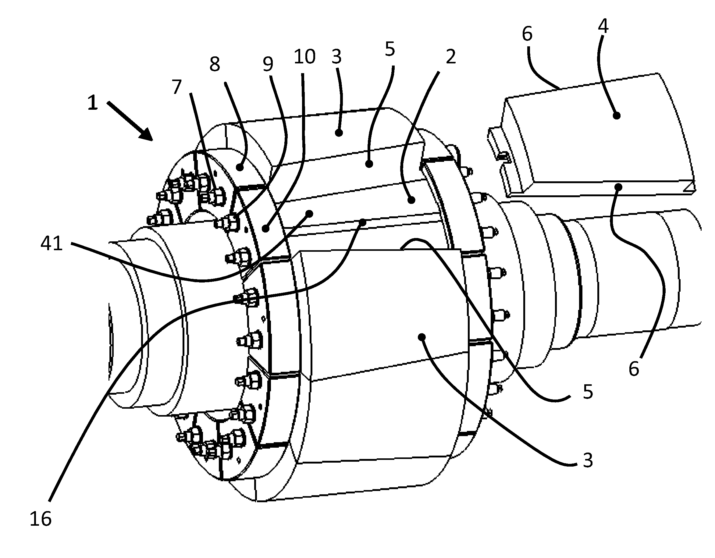
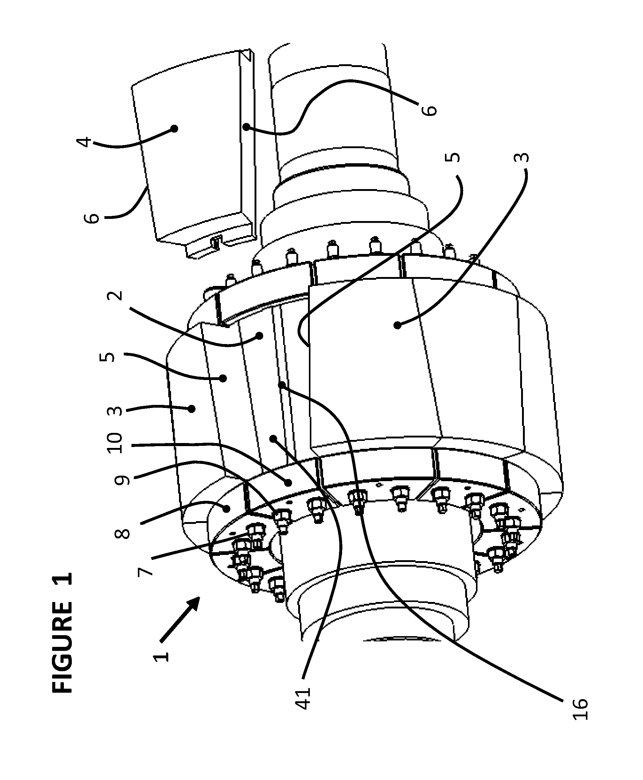
[0022]FIG. 1 shows a three-dimensional model of the preferred embodiment where a roller 1 where the outer circumference of a roller body 2 is provided with a roller shell having a plurality of individual wear segments 3, 4. The wear segments 3, 4 are trapezoidal in shape and, in the preferred embodiment, identical and, in their placement on the roller shell, rotated 180° from adjacent wear segments. Segments 3, 4 are arranged adjacent to each other on the roller body 2 for providing fixation in the circumferential direction. The non-parallel sides 5 of the initially fixed wear segment 3 and the non-parallel sides 6 of each adjacent wedged-in wear segment 4 are complementary to each other. When assembled, a number of wear segments 3 are initially fixed to the roller body 2 by fastening means in the form of screw connections 7 and clamps 8. By initially fixing the wear segments 3 in this manner, a series of spaces 41 are created between them. Initially attaching the wear segments 3 to...


PUM

PropertyMeasurementUnit
Angleaaaaaaaaaa

Abstract

Described is a roller for crushing of particulate material, such as crude ore for use in the mineral industry, where the roller body is provided with a roller shell having a plurality of individual wear segments. The roller shell is characterized in that adjacent wear segments have complementary sides and in that a number of the wear segments, prior to mounting of the remaining wear segments, are initially fixed to the roller body in order to provide guiding and fixation for the remaining wear segments which are wedged-in between the number of initially fixed wear segments.

Description

[0001]The present invention relates to a roller for the crushing of particulate material, such as crude ore for use in the cement or minerals industries, by which a roller body is provided with a roller shell comprising a plurality of individual wear segments that are wedged together in such a manner to minimize or eliminate the gaps between the segments. The invention also relates to a method of manufacturing said roller.[0002]The roller may for example be used 1) in a high-pressure grinding roller press, 2) in a vertical roller mill, 3) or in similar equipment for crushing of particulate material.BACKGROUND OF THE INVENTION[0003]Segmented crushing rollers are known from DE 197 09 263 A1, U.S. Pat. No. 5,253,816, and U.S. Pat. No. 5,860,609. These patents / applications describe rollers having the outer circumference of the roller body covered with a segmented roller shell; however, such a segmented solution is not typically used in high pressure grinding applications. This is becaus...

Claims


Application Information

Patent Timeline
IPC IPC(8): B02C4/30
CPCB02C4/305Y10T29/49549
Inventor EUCULANO, JASONBURYNSKI, RAYMOND M.
Owner FLSMIDTH AS
Why Eureka
Try Eureka