Container insert incorporating thermally insulative panels

Inactive Publication Date: 2009-01-01
NANOPORE INC
View PDF17 Cites 34 Cited by
  • Summary
  • Abstract
  • Description
  • Claims
  • Application Information

AI Technical Summary

Benefits of technology

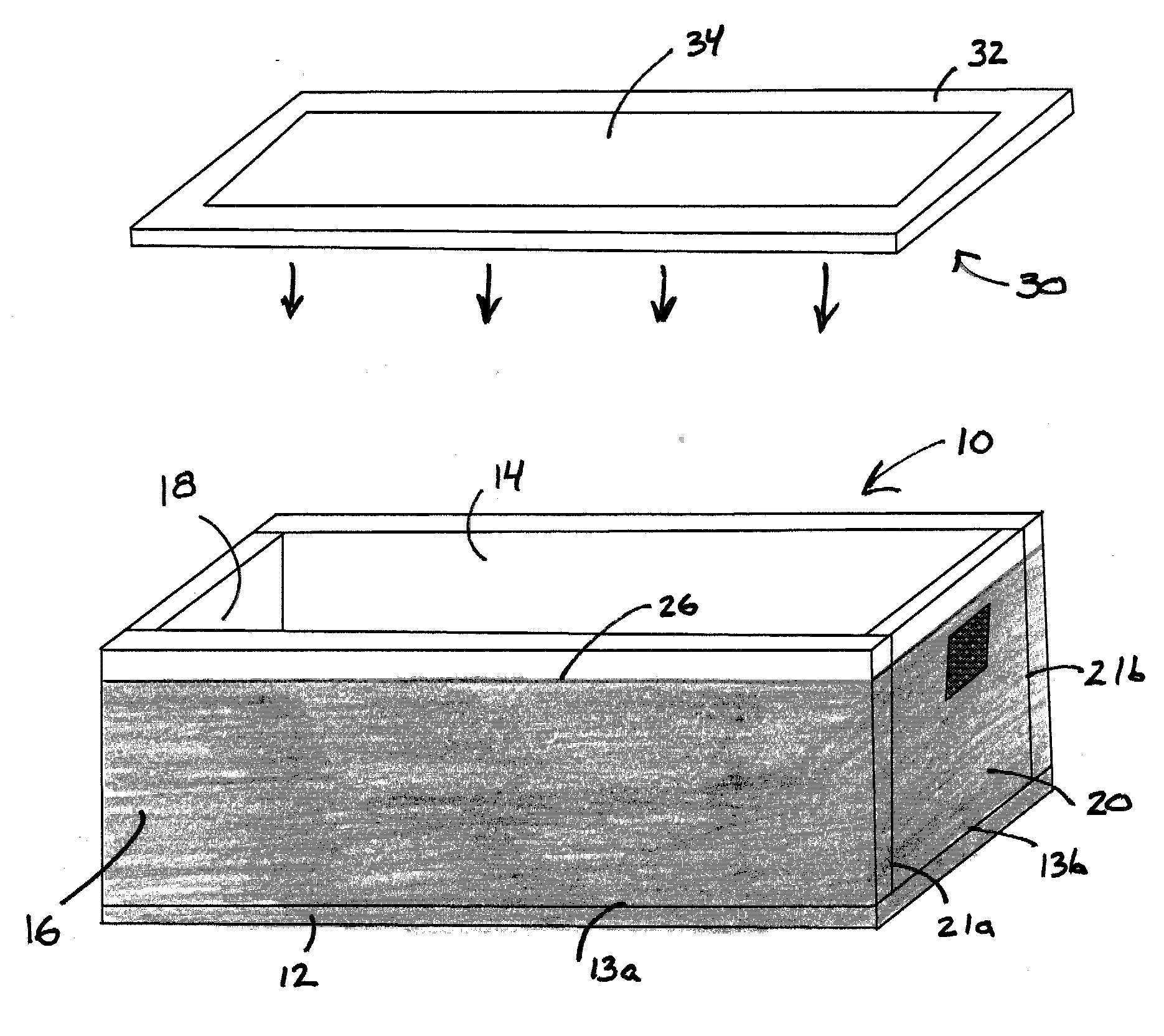
[0016]Accordingly, it is an object of the present invention to provide a thermally insulative container insert that is adapted to be placed within a container, such as a shipping container. The insert can be placed within an outer container, such as a cardboard box, to provide thermal insulation for a product placed within the container. The insert can advantageously reduce the amount of manual labor previously required to thermally insulate a container, particularly when using vacuum insulation panels. The insert can also minimize or eliminate the gaps that can exist between adjacent insulation panels to increase thermal performance by reducing thermal bridging and reducing the formation of condensation, or the formation of ice in frozen applications. For dry ice shipments in particular, ice can form within the container and increase the heat load, serve as a thermal bridge and can push adjacent panels apart. The present invention can reduce or eliminate the formation of ice by providing a tightly sealed and thermally insulated product cavity.

Problems solved by technology

The market segment for containers less than about one cubic foot in size is currently very limited due to the need for a small, lightweight cooling mechanism and due to the need to use relatively thin insulating walls to maximize the available space for the product cavity.
The high cost of shipping is at least partially related to the volume occupied by the EPS insulation.
VIPs have a high thermal resistance; however, they are much more costly than EPS sheets.
When utilizing a container or similar article that is insulated with VIPs, the highest potential for thermal losses from the container occurs at the edges and corners where two VIPs are in contact.
Having an inadequate seal along these edges can severely degrade the performance of the thermally-insulated container.
Sealing the edges of adjacent VIPs can be difficult since the standard manufacturing method for VIPs involves evacuating the panel and sealing one or more of the panel edges, which results in a flap protruding from the edge.
Accordingly, adjacent vacuum panels cannot be positioned without space between them.
Standard insulation materials, including the compressible insulation disclosed by Frysinger et al. and Lehman et al., do not provide the thermal resistance of VIPs, and will inherently contribute to thermal losses in a container that is otherwise lined with VIPs.

Method used


Image

  • Container insert incorporating thermally insulative panels
  • Container insert incorporating thermally insulative panels
  • Container insert incorporating thermally insulative panels

Examples


Embodiment Construction

[0026]The present invention is directed to a container insert and a method for using the container insert to thermally insulate products contained therein. In this regard, the container insert includes thermally insulative panels that form the walls of the container insert.

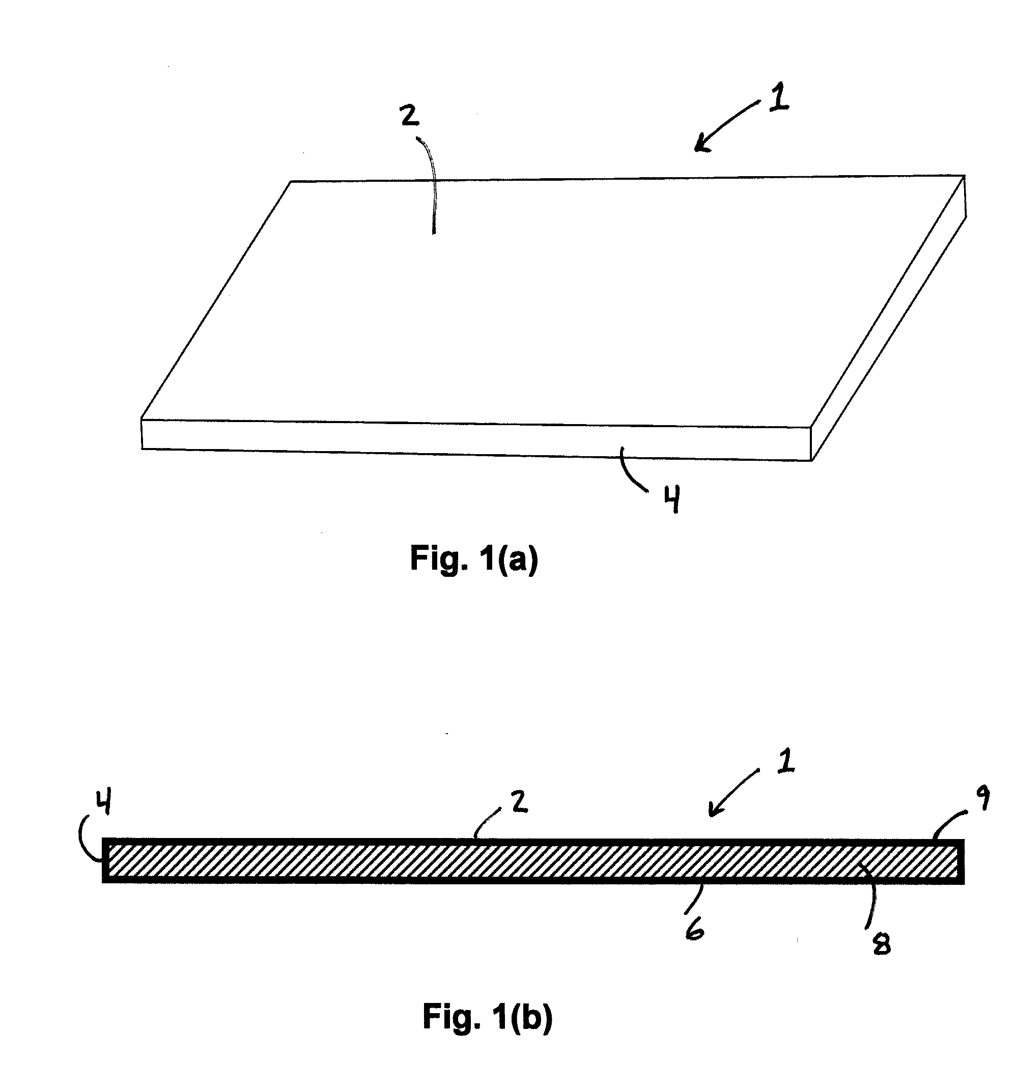
[0027]FIGS. 1(a) and 1(b) illustrate a thermally insulative panel that can be utilized in the container insert. The thermally insulative panel 1 is preferably rigid such that the panel can form a rigid wall of the container insert. The panel 1 includes a top surface 2 and a mutually opposed bottom surface 6. The thermal insulation panel also includes a peripheral edge surface 4 extending along the perimeter of the insulation panel 1. In one embodiment, the peripheral edge surface 4 can have a thickness of from about ¼ inch to about 2 inches.

[0028]In one particularly preferred embodiment, the insulative panel 1 is a vacuum insulation panel (VIP). In this regard, the insulative panel 1 includes a thermally insulativ...


PUM


Abstract

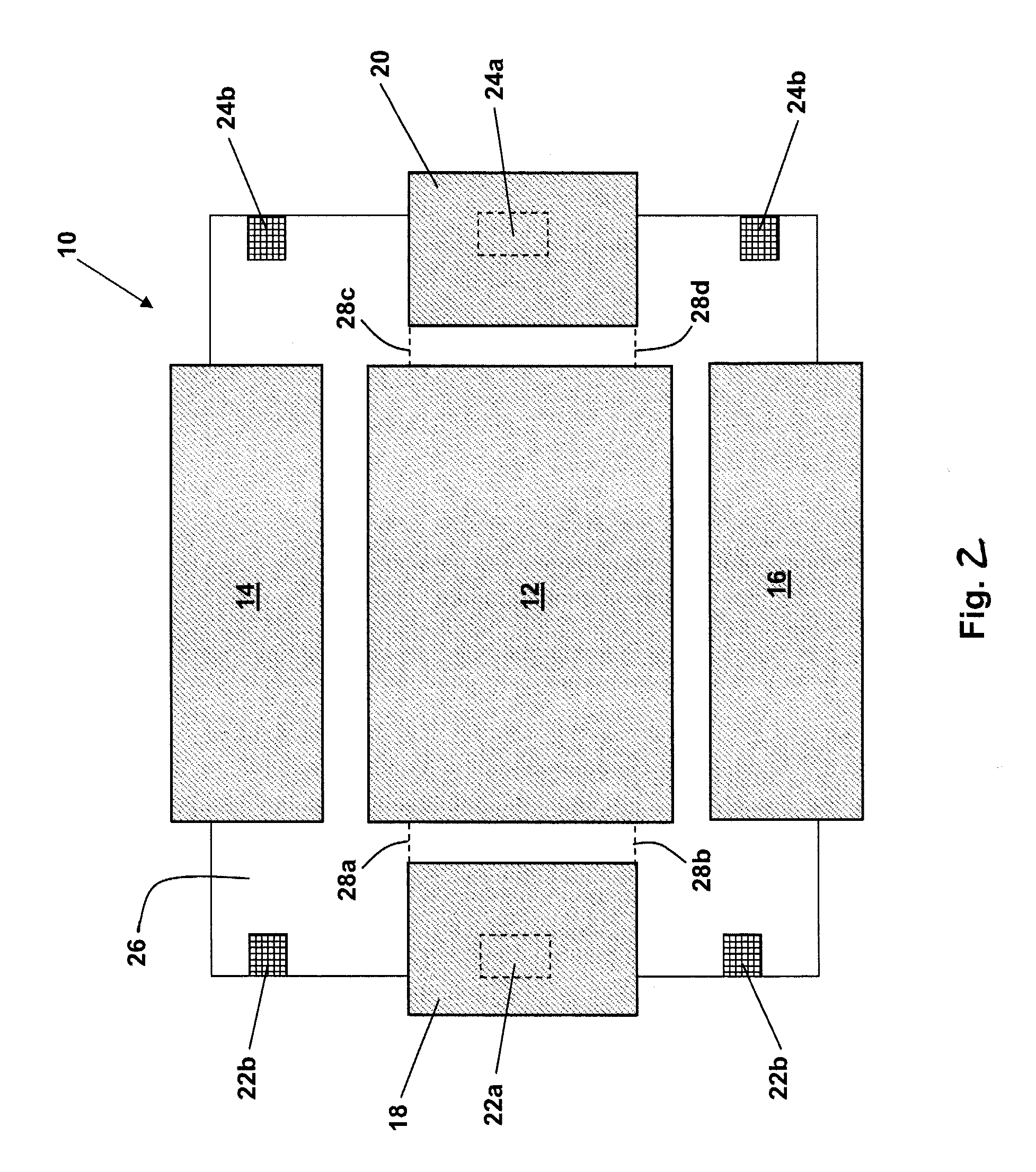
A container insert for providing a thermally insulated enclosure. The container insert includes a bottom panel, side panels and end panels that are interconnected by a plastic backing sheet. The side panels and end panels can be pivoted upwardly to form side walls and end walls. The plastic backing sheet covers the seams between adjacent insulation panels to provide a moisture barrier. The plastic backing sheet can also urge adjacent panels together to reduce the gap between adjacent panels and improve thermal performance.

Description

CROSS-REFERENCE TO RELATED APPLICATIONS[0001]This application claims priority to U.S. Provisional Patent Application Ser. No. 60 / 911,386 entitled “CONTAINER INSERT INCORPORATING THERMALLY INSULATIVE PANELS”, filed Apr. 12, 2007, the disclosure of which is incorporated herein by reference in its entirety.BACKGROUND OF THE INVENTION[0002]1. Field of the Invention[0003]The present invention relates to the field of thermally insulated containers that are adapted for the packaging, containment and / or transport of temperature sensitive goods.[0004]2. Description of Related Art[0005]Insulated containers having thermally insulated walls are utilized for the containment and / or transport of goods that can be damaged or otherwise rendered unsuitable for use if exposed to temperatures outside of a particular temperature range. Thermal insulation can be used to maintain a desired temperature within the container despite increases or decreases in the exterior (ambient) temperature.[0006]For examp...

Claims


Application Information

Patent Timeline
IPC IPC(8): B65D83/72
CPCB65D81/3851
Inventor RODERICK, KEVIN H.GLOVER, BRIANSMITH, DOUGLAS M.
Owner NANOPORE INC
Why Eureka
Try Eureka