
Modular Electric Power Distribution System

a power distribution system and module technology, applied in the direction of coupling contact members, substations, coupling device connections, etc., can solve the problems of difficult service of cables and modules, high insertion force mounting, and inconvenient service of cables, etc., to prevent inadvertent contact, and reduce the insertion force

Active Publication Date: 2014-06-12
ROCKWELL AUTOMATION TECH
View PDF1 Cites 14 Cited by
  • Summary
  • Abstract
  • Description
  • Claims
  • Application Information

AI Technical Summary

Benefits of technology

The patent is about a new type of electrical connector that has two high-current conductors and two spring clips. The conductors are made of highly conductive metal and are designed to make reliable electrical connections with other components. The spring clips are made of heat-resistant metal and secure the conductors in place to prevent arcing and accidental contact. The conductors and springs are all housed in an insulating housing to form a single piece and prevent any other components from coming into contact with any of the components. The resistance heating of the spring clips does not change the contact pressure. These new connectors provide a reliable and safe way to connect high-current components.

Problems solved by technology

However, connecting each module to the power source using pairs of heavy-duty cables for each required type of electric power is difficult, expensive and inconvenient.
This is a time-consuming and expensive process.
Servicing the cables and modules can be difficult.
High amperage current flowed through conventional bridge assemblies can heat and weaken the copper U-bends sufficiently to reduce contact pressure between the conductor strips and the contact members.

Method used


Image

  • Modular Electric Power Distribution System
  • Modular Electric Power Distribution System
  • Modular Electric Power Distribution System

Examples


Embodiment Construction

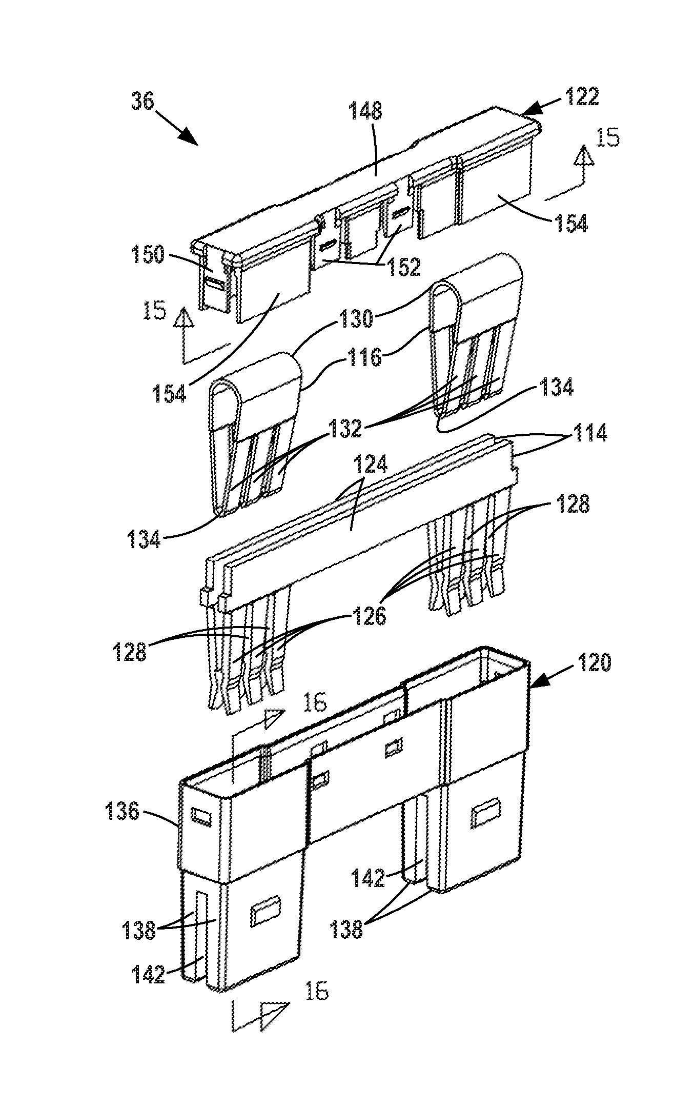
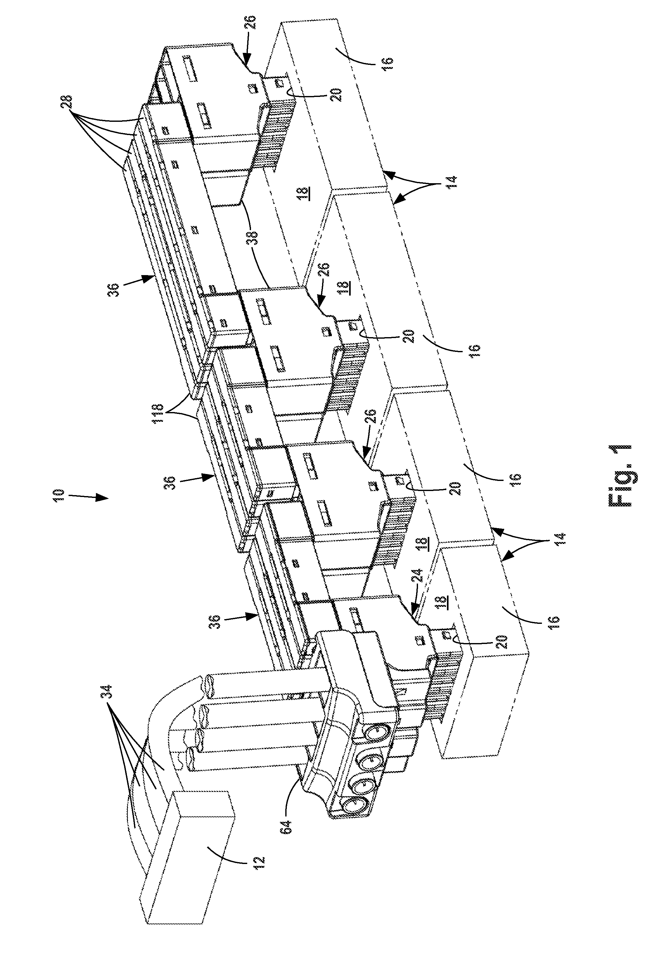
[0032]FIG. 1 illustrates a modular electric power distribution system 10 according to the invention. The FIG. 1 system forms two conductor electrical connections between an electric power source 12 and four or more control modules 14. Each control module includes a rectangular body 16 with a top surface 18 and a mounting opening 20 formed in top surface 18. The openings 20 are aligned in a row on surfaces 18. Power contacts 22 are located in modules 14 below openings 20 for forming electrical connections with contacts in the lower portions of power distribution units 24 and 26 which extend into openings 20.

[0033]Each control module 14 is connected to an electric step motor or other power consumer. The module includes an actuator circuit which determines when power is required to be supplied to the step motor or consumer, or when power from the step motor or consumer is returned back to system 10. The components of modules 14 and the actuator circuits are not illustrated.

[0034]The po...


PUM


Abstract

A modular electric power distribution system transmits power between a power source and control modules for power consumers. The system includes a power distribution unit mounted on each module and bridge assemblies which connect adjacent distribution units.

Description

FIELD OF INVENTION[0001]The invention relates to a modular electric power distribution system for transmitting electric power between a power source and control modules for power consumers, which may be electric step motors. Power is transmitted in response to input signals received by circuitry in the control modules. A number of types of electric power may be transmitted between the power source and the modules. Each type of power is distributed to the modules depending upon the needs of power consumers controlled by the modules. Power may be transmitted from a power consumer back into the distribution system.BACKGROUND OF THE INVENTION[0002]Electric power control modules supply power to step motors in response to input signals received by the modules. Each module may supply a number of different types of power. Conventionally, each module is connected to a power source by heavy-duty power cables. Two cables are required for each type of power supplied to a module. Each module inc...

Claims


Application Information

Patent Timeline
Patent Type & Authority Applications(United States)
IPC IPC(8): H02G5/02
CPCH02G5/02H01R9/2458H01R13/18H01R31/02H01R31/06H01R31/08H01R13/514H01R9/2675H01R31/085H01R13/627H02B7/00H02G5/025
Inventor BILLMAN, TIMOTHY BRIANFAULKNER, SCOTT ANTHONYWIEST, SHANE
Owner ROCKWELL AUTOMATION TECH
Learn More