
Measuring and Displaying Tractor Performance

a technology of tractors and tractors, applied in the field of large tracktype tractors, can solve the problems of increasing the cost of owning and operating a large piece of earthmoving equipment, difficult to measure factors that affect efficient use, and high cost, so as to improve performance and optimize performan

Active Publication Date: 2014-06-05
CATERPILLAR INC
View PDF2 Cites 16 Cited by
  • Summary
  • Abstract
  • Description
  • Claims
  • Application Information

AI Technical Summary

Benefits of technology

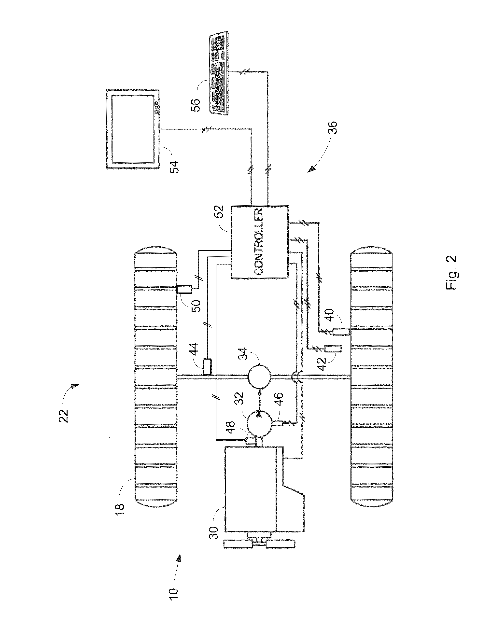
The patent describes a system that uses sensors to collect data on the ground speed, track speed, slope, and gear of a track-type tractor. A processor then uses this information to calculate adjustment factors for a pull-slip curve and an optimum operating state for the current operating condition. This optimum state is then output to a device that can adjust the operating state of the tractor to improve performance. The technical effect of the system is to provide a more efficient and effective means of controlling the track-type tractor to enhance performance.

Problems solved by technology

Owning and operating a large piece of earthmoving equipment can be expensive.
Operating cost is a function of efficient use and the impact of carrying too small or too large a load, operating in the wrong gear, etc., can dramatically increase that cost.
However, the factors that impact efficient use are often hard to measure because soil conditions, operator selections such as gear and engine speed, and ground slope at the worksite all effect efficiency.
Further, operators are often provided with an overload of information intended to improve efficiency but which may often simply overwhelm the operator and cause them to ignore potentially useful information.

Method used


Image

  • Measuring and Displaying Tractor Performance
  • Measuring and Displaying Tractor Performance
  • Measuring and Displaying Tractor Performance

Examples


Embodiment Construction

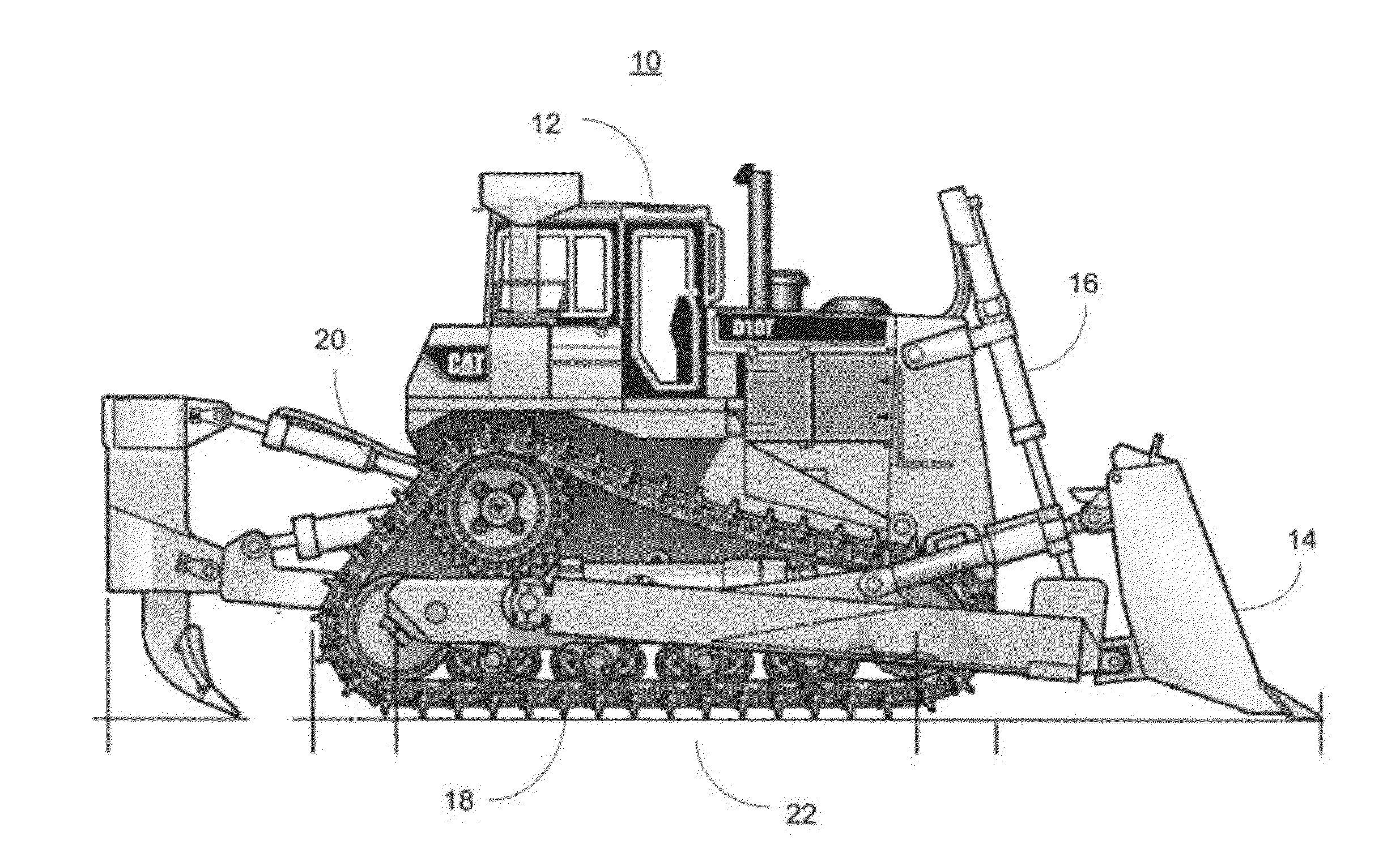
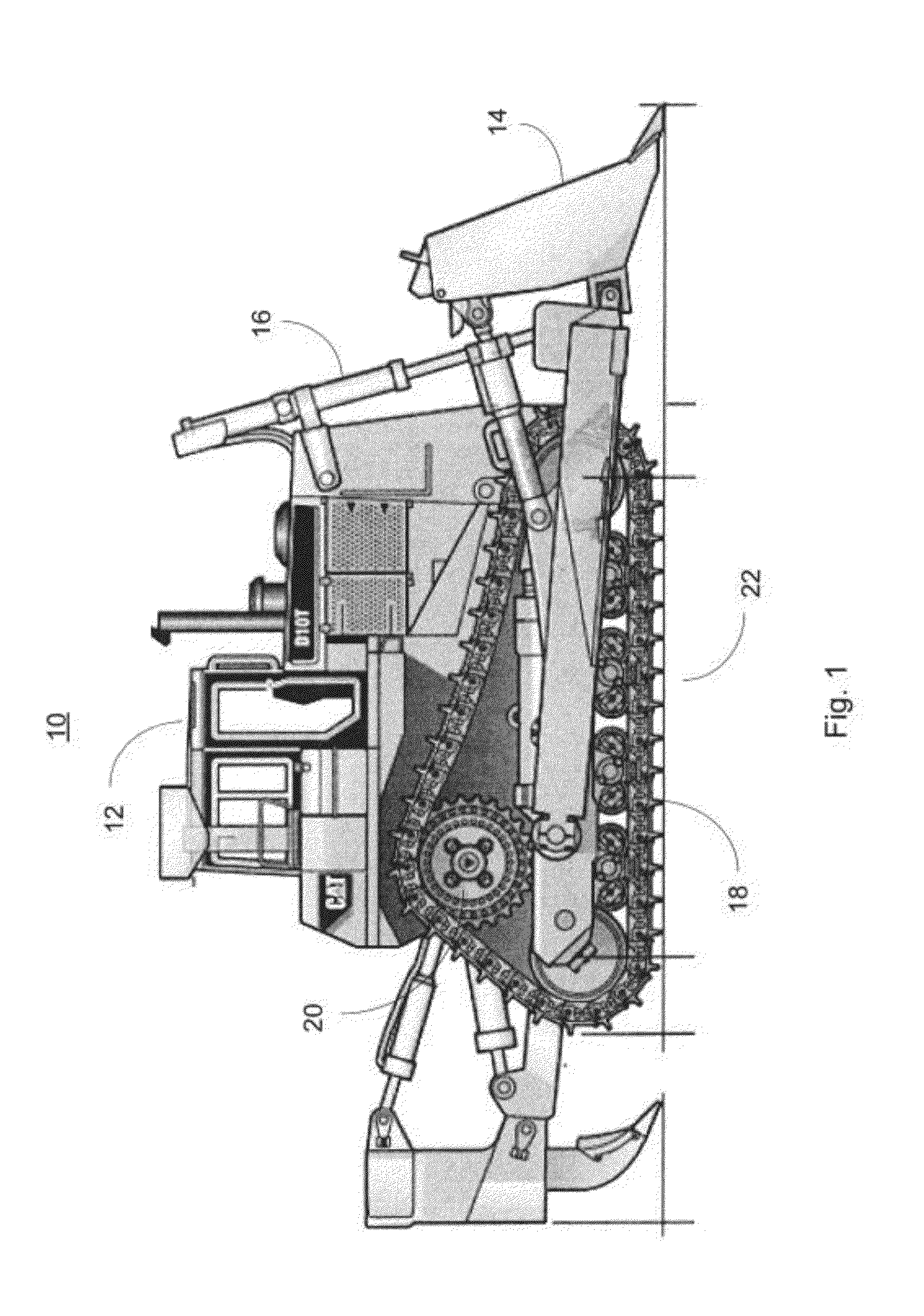
[0029]Most major construction projects and many smaller projects require reshaping the earth on or around the worksite. Earth moving equipment comes in many shapes and sizes including, but not limited to, graders, backhoes, earthmovers, and bulldozers. Each of these different types of equipment is targeted to specific tasks related to earth moving. This disclosure is generally directed to a category of equipment referred to as track-type tractor and more specifically large track-type tractors using a front blade, such as a bulldozer.

[0030]In analyzing the performance of such machines, two major elements are at play, the operating conditions and the operating state. The operating condition or environment is generally described as those things outside the operator's control and include, but are not limited to, the slope of the work area, the material being moved, and the distance the material is moved, known as the cycle distance. Operating conditions also include the characteristics ...


PUM


Abstract

A method of measuring and displaying track-type tractor performance in real time calculates both a measure of work performance and a theoretical optimum work performance for a given input state, such as track speed. After estimating soil conditions, the theoretical optimum is estimated using an iterative technique. The optimum and current performance are normalized and displayed using a first bar representing a full range of work performance, a second bar depicting a range of optimum performance for current conditions is presented overlying the first bar, and an indicator line showing the current performance. This allows an operator to adjust speed or load accordingly. A coefficient of traction and a shear modulus adjustment, reflecting soil conditions, are calculated at the tractor during operation and used to offset a table of ideal condition operating points to produce the second bar.

Description

TECHNICAL FIELD[0001]The present disclosure generally relates to large track-type tractors and more specifically to measuring and displaying performance of track-type tractors during operation.BACKGROUND[0002]Owning and operating a large piece of earthmoving equipment can be expensive. Operating cost is a function of efficient use and the impact of carrying too small or too large a load, operating in the wrong gear, etc., can dramatically increase that cost. However, the factors that impact efficient use are often hard to measure because soil conditions, operator selections such as gear and engine speed, and ground slope at the worksite all effect efficiency. Further, operators are often provided with an overload of information intended to improve efficiency but which may often simply overwhelm the operator and cause them to ignore potentially useful information.[0003]For example, U.S. Pat. No. 7,557,726 presents, among a number of other items, a numerical indication of actual condi...

Claims


Application Information

Patent Timeline
IPC IPC(8): B60W10/04
CPCB60W10/04B60W50/0098B60W50/14B60K35/00B60W2050/0031B60W2050/146B60W2300/17B60W2510/1005B60W2520/10B60W2520/26Y02T10/84B60K35/28B60K2360/174
Inventor FAIVRE, JOSEPHDOY, NATHANIELCOWPER, LANCE
Owner CATERPILLAR INC
Learn More