Image generation apparatus

a technology of image generation and apparatus, applied in image enhancement, tomography, instruments, etc., can solve the problems of undesirable appearance and general unwoidness of relative noise image, and achieve the effect of improving noise appearan

Active Publication Date: 2014-06-05
KONINKLIJKE PHILIPS ELECTRONICS NV
View PDF4 Cites 6 Cited by
  • Summary
  • Abstract
  • Description
  • Claims
  • Application Information

AI Technical Summary

Benefits of technology

[0003]It is an object of the present invention to provide an image generation apparatus, an image generation method and an image generation computer program for generating an image of an object, which allow generating an image having an improved noise appearance.
[0008]Since the combining unit generates a combination image by combining the first image and the second image depending on the window width of the provided display window, the influence of the display window on the noise appearance can be considered. In particular, by taking into account the first image and the second image having different noise levels and the provided display window, a combined image can be generated having an improved noise appearance.
[0011]It is preferred that the image providing unit is adapted to provide an image having been reconstructed from measured raw data being indicative of the object by using a first reconstruction method as the first image and an image having been reconstructed from the measured raw data by using a second reconstruction method as the second image. It is further preferred that the first reconstruction method is an iterative reconstruction method and the second reconstruction method is an analytical reconstruction method. In particular, the analytical reconstruction method is a filtered backprojection reconstruction method. By using an iterative reconstruction method for reconstructing the first image a first image can be reconstructed having a noise level being substantially zero. However, an image having a noise level of substantially zero may have an undesirable look-and-feel appearance. It may, for example, look painted or flat. In contrast, if the second image is reconstructed by using an analytical reconstruction method, in particular, a filtered back-projection reconstruction method, the second image can have a relatively large noise level. By using first and second images having such different noise levels, a combined image can be generated having a desired noise appearance for a relatively large range of possible window widths of display windows.
[0014]Preferentially, the combining unit is adapted to determine a first weight for weighting the first image and a second weight for weighting the second image depending on the provided display window, to weight the first image with the first weight and the second image with the second weight, and to sum the weighted first and second images. This allows, for example, fading the second image into the first image or vice versa in a relatively simple way.
[0015]It is preferred that the combining unit is adapted to combine a first amount of the first image with a second amount of the second image, if the display window is narrower, and to combine a third amount of the first image with a fourth amount of the second image, if the display window is wider, wherein the first amount is larger than the third amount and the second amount is smaller than the fourth amount. For example, if the first image is an iteratively reconstructed image and the second image is an image, which has been reconstructed by using a filtered back-projection reconstruction method, for a relatively narrow display window, only a relatively small amount of the second image should be faded into the first image, because otherwise the noise becomes too dominant. On the other hand, for a relatively wide display window a larger amount of the second image should be faded into the first image, because otherwise the noise level is so low that the resulting combined image has a flat look-and-feel appearance. By combining a larger amount of the first image with a smaller amount of the second image, if the display window is narrower, and by combining a smaller amount of the first image with a larger amount of the second image, if the display window is wider, a combined image can be generated, which does not have too dominant noise and which does not have a flat look-and-feel appearance. In other words, a combined image having desired noise can be generated, if for a narrower display window the combined image contains a relatively small amount of the second image and if for a wider display window the combined image contains a relatively large amount of the second image.
[0017]In a further embodiment, the combining unit can be adapted to combine the first image and the second image such that the amount of the first image decreases and the amount of the second image increases with increasing window width of the display window for window widths being smaller than a third threshold window width, and to combine the first image and the second image such that the amount of the first image increases and the amount of the second image decreases with increasing window width of the display window for window widths being equal to or larger than the third threshold window width. Also in this embodiment, the increase and the decrease can be limited to certain regions of the window width, which can be defined by window width thresholds. For example, the combining unit can be adapted to combine the first image and the second image such that the amount of the first image decreases and the amount of the second image increases with increasing window width of the display window for window widths being smaller than the third threshold window width and larger than a fourth threshold window width, and / or to combine the first image and the second image such that the amount of the first image increases and the amount of the second image decreases with increasing window width of the display window for window widths being equal to or larger than the third threshold window width and smaller than a fifth threshold window width. Since the amount of the first image, which contributes to the combined image, firstly decreases in a first window width region and then increases in a second window width region with increasing window width, in the first window width region an increasing part of the second image having the larger noise level contributes to the combined image, in order to obtain a combined image having desired noise. However, if the window width becomes larger, i.e. if the window width is within the second window width region, also in the second image noise may not be visible anymore and it may be more important to provide high contrast, which may be obtained by using a larger amount of the first image having a lower noise level. Thus, by firstly decreasing the amount of the first image and then increasing the amount of the first image, a combined image having desired noise can be obtained, wherein for relative large window widths the combination of the first and second images can be performed such that the contrast is improved.

Problems solved by technology

A relatively noisy image is generally not desired, and an image having substantially no noise has an undesirable look-and-feel appearance.

Method used


Image

  • Image generation apparatus
  • Image generation apparatus
  • Image generation apparatus

Examples


Embodiment Construction

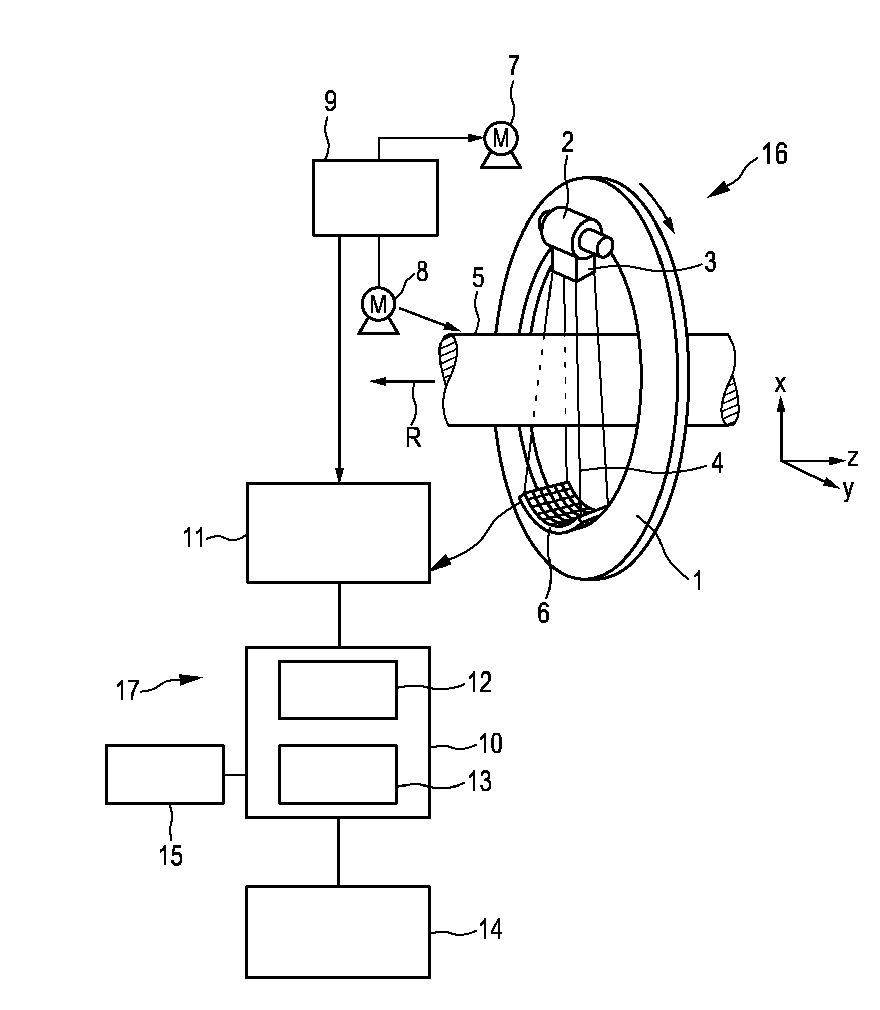
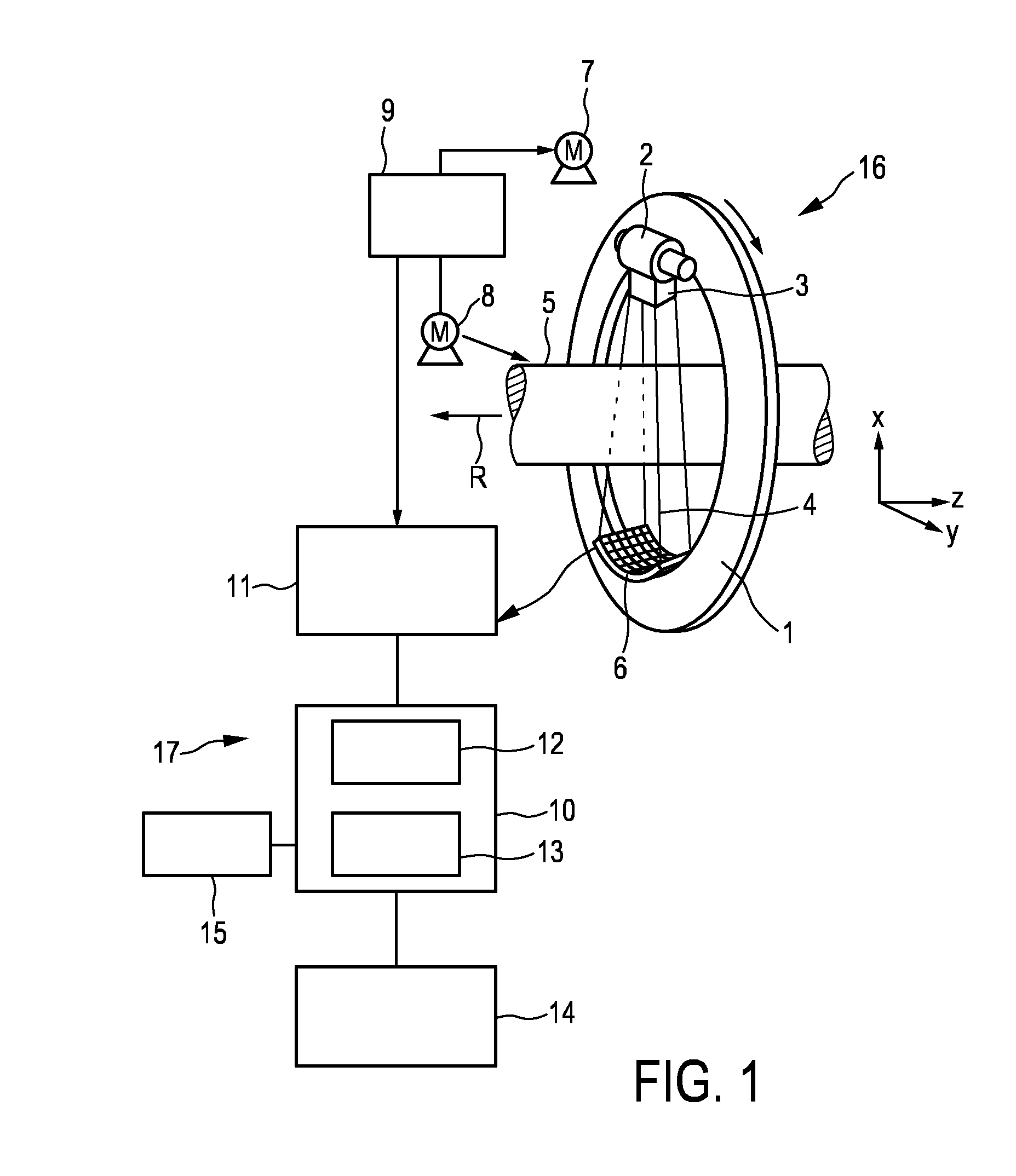
[0027]FIG. 1 shows schematically and exemplarily an embodiment of an image generation apparatus for generating an image of an object. In this embodiment, the image generation apparatus is a computed tomography apparatus. The computed tomography apparatus 17 includes a gantry 1 which is capable of rotation about a rotational axis R which extends parallel to a z direction. A radiation source 2, which is, in this embodiment, an x-ray tube, is mounted on the gantry 1. The radiation source 2 is provided with a collimator 3, which forms, in this embodiment, a conical radiation beam 4 from the radiation generated by the radiation source 2. The radiation traverses an object (not shown), such as a patient, in an examination zone 5 which is, in this embodiment, cylindrical. After having traversed the examination zone 5 the radiation beam 4 is incident on a detection device 6, which comprises a two-dimensional detection surface. The detection device 6 is mounted on the gantry 1.

[0028]The compu...


PUM


Abstract

The invention relates to an image generation apparatus for generating an image of an object. An image providing unit (11, 16) provides a first image of the object and a second image of the object, wherein the first image has a smaller noise level than the second image. A display window providing unit (12) provides a display window being indicative of the range of image values shown on a display (14), and a combining unit (13) generates a combination image by combining the first image and the second image depending on the window width of the provided display window. This allows considering the influence of the display window on the noise appearance. Thus, by taking into account the first image and the second image having different noise levels and the provided display window, a combined image can be generated, which has an improved noise appearance.

Description

FIELD OF THE INVENTION[0001]The invention relates to an image generation apparatus, an image generation method and an image generation computer program for generating an image of an object.BACKGROUND OF THE INVENTION[0002]In the field of computed tomography generally a radiation source is rotated around an object to be imaged and radiation emitted by the radiation source and having traversed the object is detected by a detector for generating projection data for different rotational positions of the radiation source with respect to the object. An image of the object can be generated from the projection data by using a reconstruction algorithm. For example, by using a filtered back-projection algorithm a relatively noisy image can be reconstructed, whereas by using an iterative reconstruction algorithm an image can be reconstructed having substantially no noise. A relatively noisy image is generally not desired, and an image having substantially no noise has an undesirable look-and-f...

Claims


Application Information

Patent Timeline
Patent Type & Authority Applications(United States)
IPC IPC(8): G06T11/00G06T5/50
CPCG06T5/50G06T11/008A61B6/032A61B6/037A61B6/463A61B6/465A61B6/5205A61B6/5235A61B6/5258G06T5/002G06T2207/10081G06T2207/30004
Inventor KOEHLER, THOMAS
Owner KONINKLIJKE PHILIPS ELECTRONICS NV
Why Eureka
Try Eureka