
Method for controlling a resonant-mode power supply and a resonant-mode power supply with a controller

a technology of resonant-mode power supply and controller, which is applied in the direction of electric variable regulation, process and machine control, instruments, etc., can solve the problems of not taking full advantage of the control utilizing self-oscillation of the resonant circuit, and the majority of resonant-mode power supplies are not capable of proper stabilization of voltage, current or output power over the entire load range, etc., to achieve the effect of increasing the switching frequency of the switch assembly

Inactive Publication Date: 2014-05-29
ACAD GORNICZO HUTNICZA IM STANISLAWA STASZICA
View PDF1 Cites 24 Cited by
  • Summary
  • Abstract
  • Description
  • Claims
  • Application Information

AI Technical Summary

Benefits of technology

The patent text describes a circuitry that helps increase the switching frequency of a switch assembly. This circuitry uses a fast-response circuit to monitor the current of a recirculation circuit and works through a controller. This results in quicker and more efficient switching of the switch assembly.

Problems solved by technology

Most of resonant-mode power supplies are not capable to provide proper stabilization of voltages, currents or output power over the entire load range, i.e. from the open to shorted output.
Although all the above methods are useful, they do not take full advantages offered by the control utilizing self-oscillations of the resonant circuit.

Method used


Image

  • Method for controlling a resonant-mode power supply and a resonant-mode power supply with a controller
  • Method for controlling a resonant-mode power supply and a resonant-mode power supply with a controller
  • Method for controlling a resonant-mode power supply and a resonant-mode power supply with a controller

Examples


Embodiment Construction

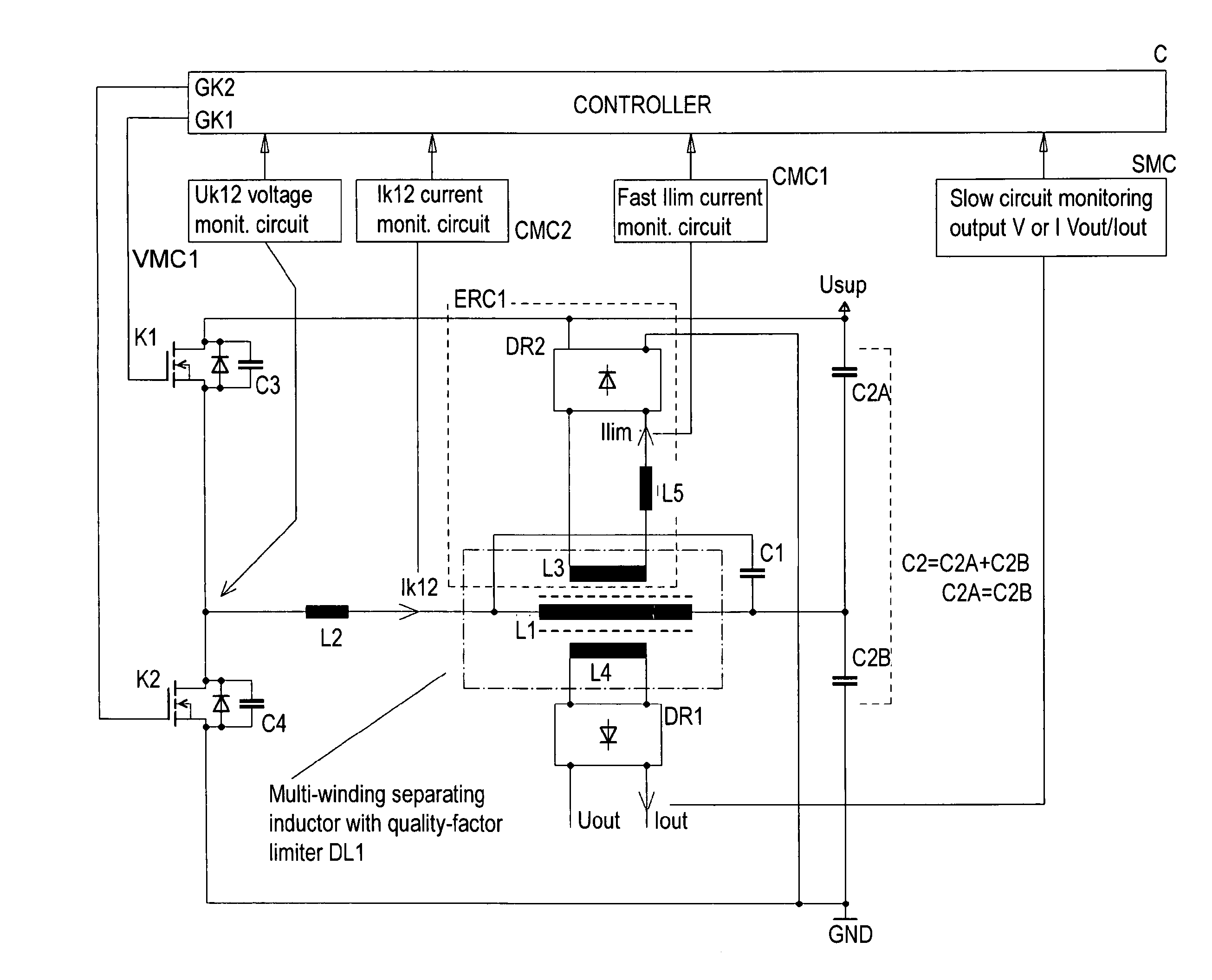
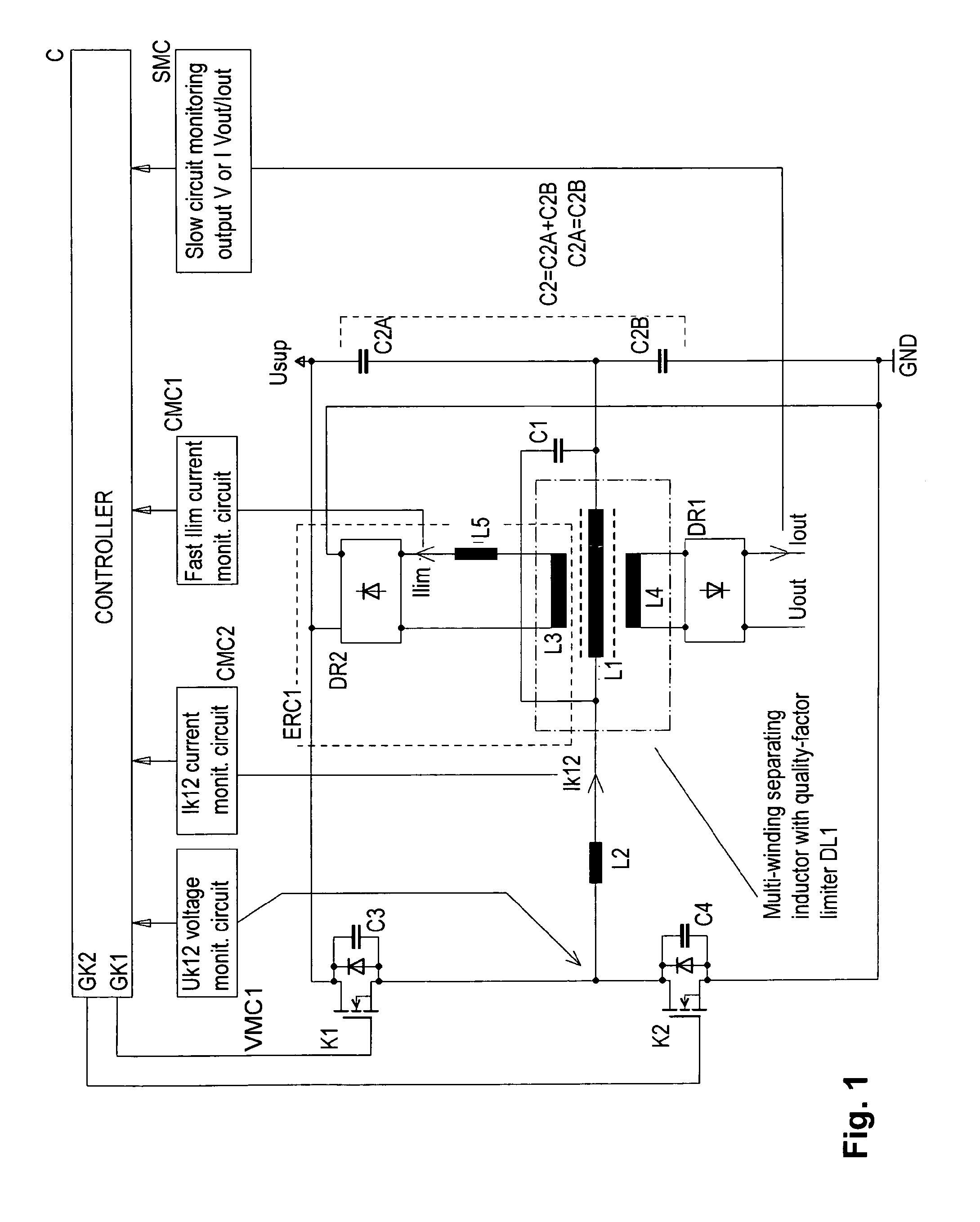
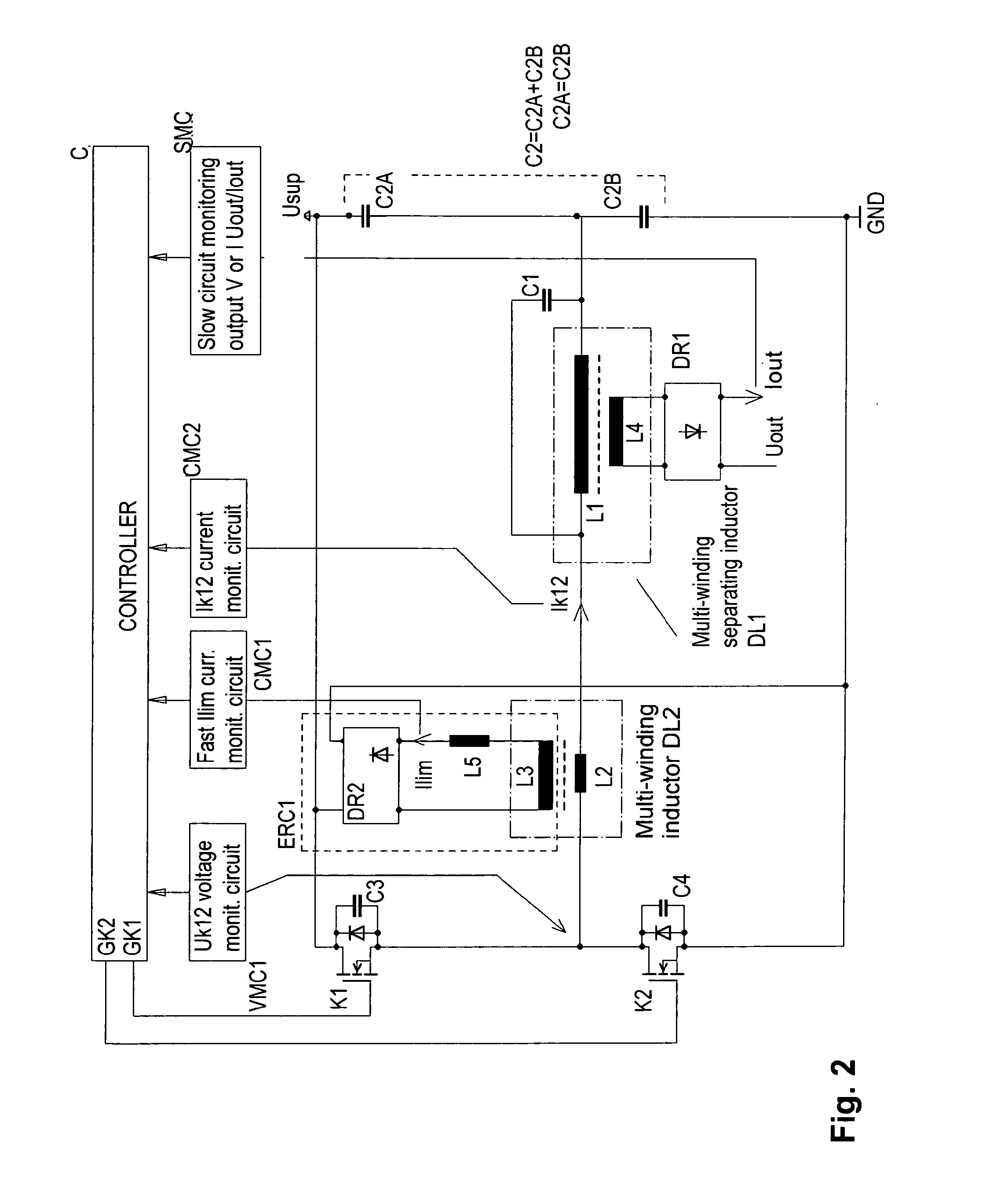
[0030]FIG. 1 shows the first exemplary embodiment of the resonant-mode power supply with a controller, as a half-bridge resonant converter with a quality-factor limiter incorporating a multi-winding inductor DL1 having a magnetic circuit which contains an air gap. The resonant-mode power supply comprises an assembly of switches K1, K2 connected into a half-bridge configuration. In the diagonal of the half-bridge there is connected a series-parallel resonant circuit comprised of inductor L2, capacitance C1, parallel connection of capacitances C2A and C2B that constitute the resultant capacitance C2, and inductor L1 being a part of the multi-winding inductor DL1 which isolates the quality-factor limiter winding L3, and the load circuit winding L4 by means of which a load is connected through a diode rectifier DR1 to the resonant-mode power supply. The inductor L2 together with the resultant capacitance C2 of the parallel-connected capacitances C2A and C2B form the series resonant circ...


PUM


Abstract

A method for controlling a resonant-mode power supply, the resonant-mode power supply comprising an assembly of switches (K1, K2, K3, K4), between which a resonant circuit with an output load is connected, and a controller (C) configured to stabilize output voltages or currents by controlling switching frequency of the assembly of switches (K1, K2, K3, K4) in response to the output of a slow-response monitoring circuit (SMC) configured to monitor the output voltage or current and having a certain time (τ1) of response to changes of value of the output voltage or current. The power supply further comprises an energy recirculation circuit (ERC1) in which the current (Ilim) is monitored by means of a fast-response monitoring circuit (CMC1) having a time (τ2) of response to changes in the (Ilim) current faster than the response time (τ1) of the slow-response monitoring circuit (SMC). The method involves adjusting, via the controller (C), the switching frequency of the assembly of switches (K1, K2, K3, K4) such as to reduce the power supplied to the resonant circuit upon exceeding a threshold value by the current (Ilim).

Description

TECHNICAL FIELD[0001]The present invention relates to a method for controlling a resonant-mode soft-switched power supply and to a resonant-mode power supply with a controller intended for stabilization of the output voltage, current or power.BACKGROUND ART[0002]Most of resonant-mode power supplies are not capable to provide proper stabilization of voltages, currents or output power over the entire load range, i.e. from the open to shorted output. In general, any of these states, or both of them, can be regarded as the most adverse operating conditions. To remedy this problem, resonant power circuit configurations are modified by means of e.g. providing additional energy recirculation circuits that enable feeding energy from the resonant circuit back to the supply or employing advanced circuits for controlling switches.[0003]The Polish patent application P-349476 discloses a method for the output voltage and current control in power supplies provided with circuits feeding excess ene...

Claims


Application Information

Patent Timeline
IPC IPC(8): H02M3/335H02M1/00
CPCH02M3/33507H02M3/3376Y02B70/10H02M1/0032H02M1/0058H02M3/33553H02M7/4818
Inventor WOREK, CEZARY
Owner ACAD GORNICZO HUTNICZA IM STANISLAWA STASZICA
Learn More