
Rail plasma actuator for high-authority flow control

a plasma actuator and actuator technology, applied in the direction of air-flow influencers, mechanical devices, transportation and packaging, etc., can solve the problems of poor aerodynamic flow actuation authority of most existing atmospheric-pressure flow control applications such as dbd, and the limited bandwidth (or response time) of flow control devices with much higher bandwidth and faster response times, so as to reduce the likelihood of localized thermal hotspots, avoid structural problems or disruptions of surface aerodynamics, and simple device

Inactive Publication Date: 2014-05-29
BOARD OF RGT THE UNIV OF TEXAS SYST
View PDF19 Cites 9 Cited by
  • Summary
  • Abstract
  • Description
  • Claims
  • Application Information

AI Technical Summary

Benefits of technology

The present disclosure addresses the problem of plasma flow control in various applications such as aircraft wing surfaces, gas turbine engines, and helicopters. The invention provides a simple device without moving parts and a plasma armature that moves rapidly along rails without developing localized thermal hotspots on the surface. The plasma armature velocity is very high, and the induced gas flow velocity is commensurately high, providing high momentum fluxes imparted to the flow. The invention can be used to prevent flow separation under high angle of attack aircraft maneuvers, reduce duct pressure losses, prevent tip leakage losses, and improve helicopter performance. The plasma armature formation and propagation down the rails can be repeated in rapid succession to form a quasi-continuous wall jet. The invention can also mitigate the formation of vortices proximal to an end of the airfoil.

Problems solved by technology

The bandwidth (or response times) of these mechanical flow control devices is however limited, and there is a need for flow control devices with much higher bandwidth and faster response times. Moreover, there is need for flow control devices that do not involve moving parts and are minimally intrusive to the surface structure on which they are mounted.
Most existing technologies for atmospheric-pressure flow control applications such as DBD suffer from very poor aerodynamic flow actuation authority, with induced velocities not exceeding a few m / s.
Consequently, the momentum transferred to the flow by the actuators is too small to be useful for most aerodynamic flow control applications.
However, these devices suffer structural issues due to cavity penetration within surfaces and localized hot-spots within the cavity.
In addition, exemplary embodiments comprise a plasma armature that moves rapidly along the rails and reduces the likelihood of developing localized thermal hotspots on the surface.
Exemplary embodiments also do not create localized thermal hot-spots and provide for higher induced flow velocities (momentum fluxes) than current plasma flow actuation and control technologies.

Method used


Image

  • Rail plasma actuator for high-authority flow control
  • Rail plasma actuator for high-authority flow control
  • Rail plasma actuator for high-authority flow control

Examples


Embodiment Construction

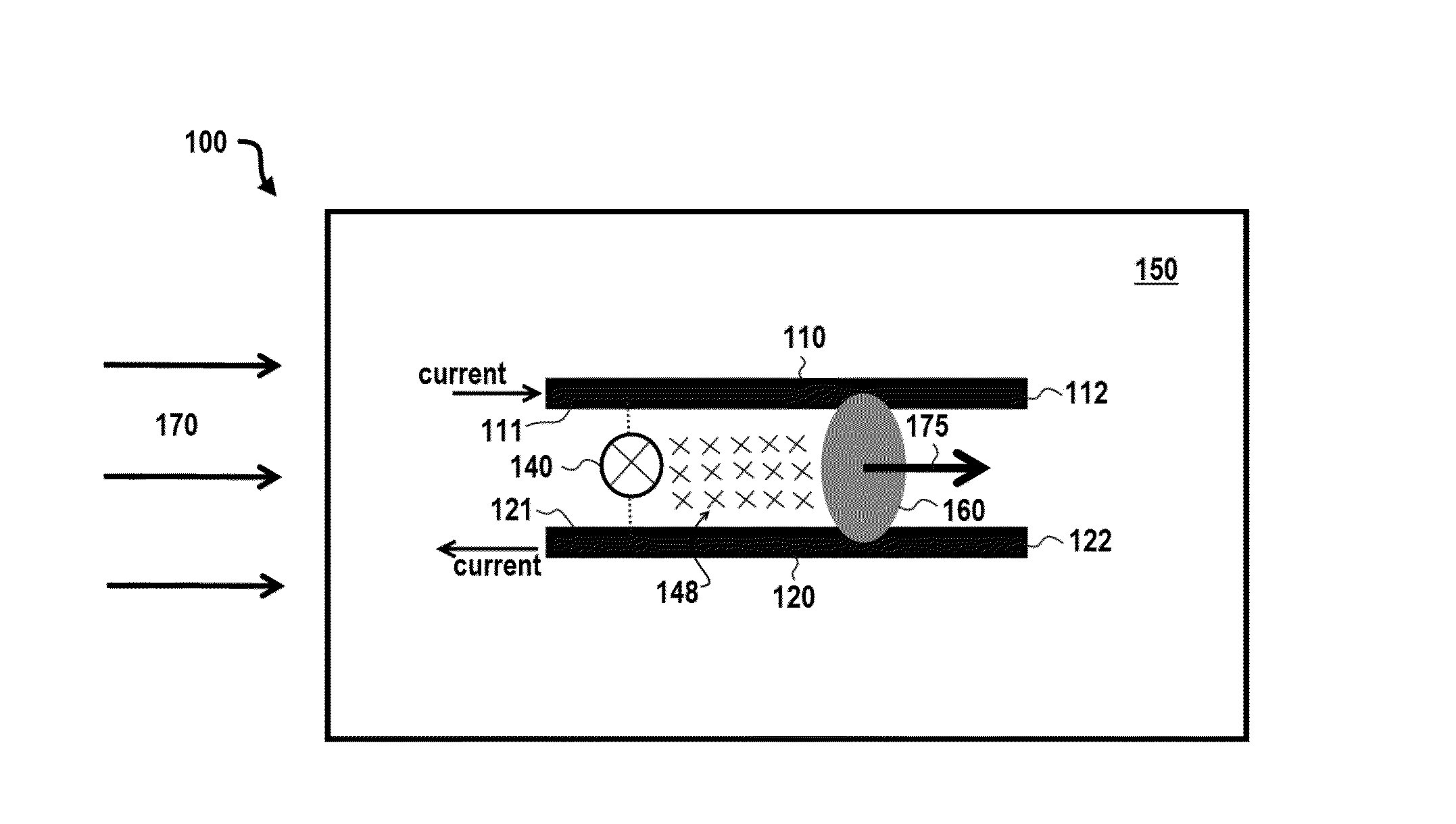
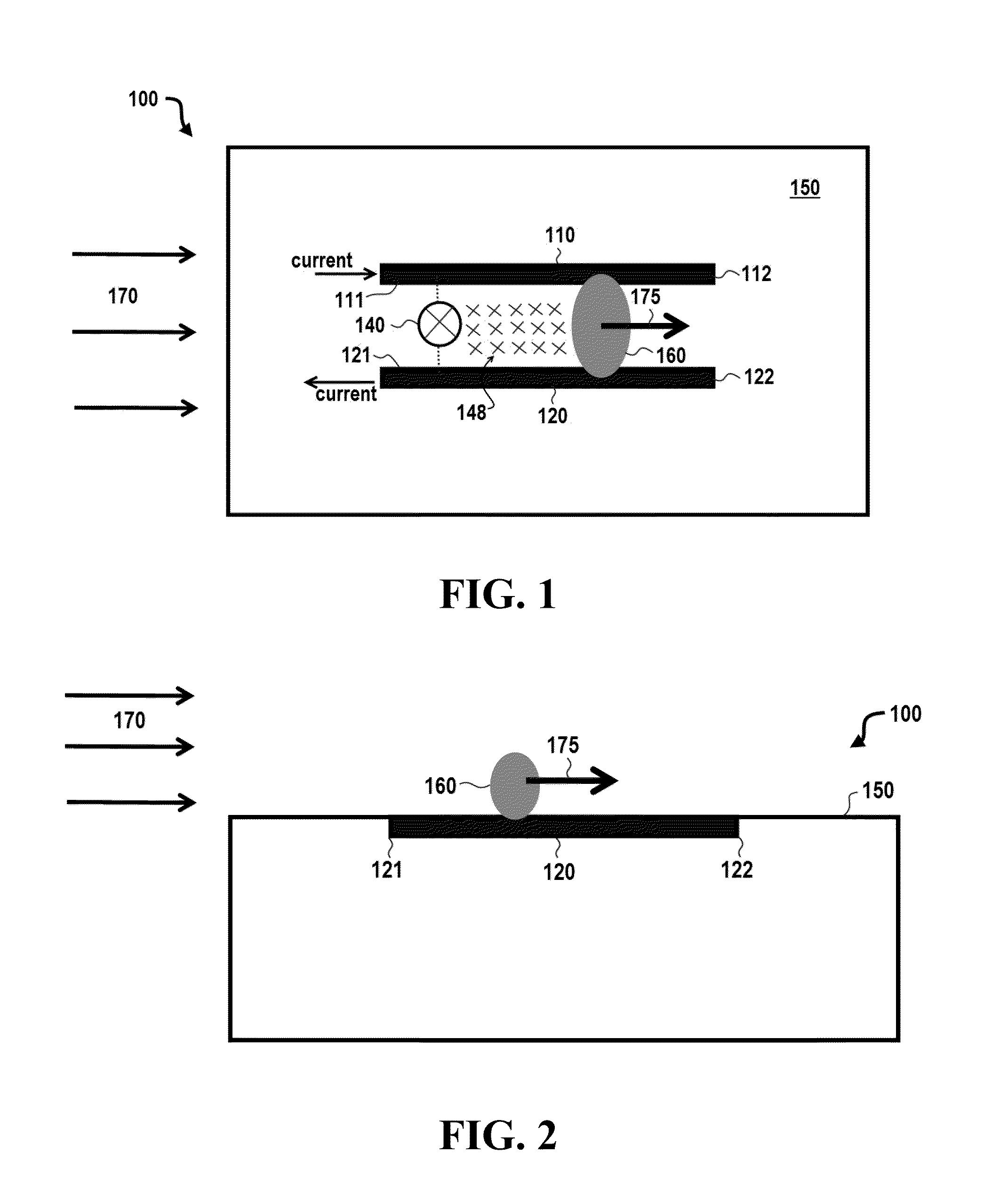
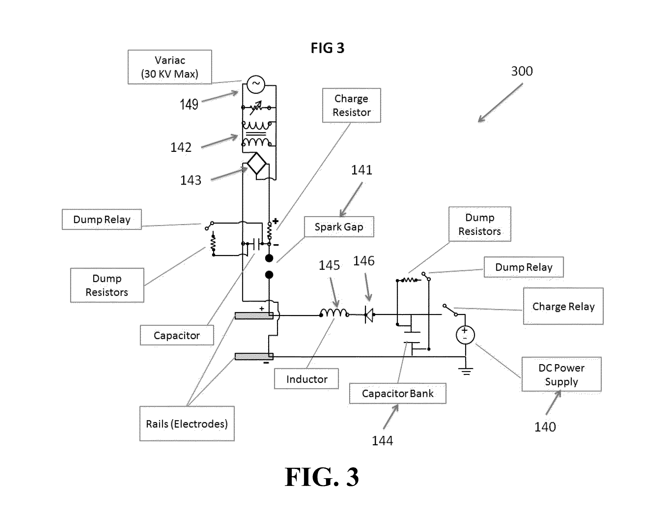
[0035]Referring now to FIGS. 1-3, an apparatus 100 comprises a surface 150 configured to allow a gas 170 to flow over the surface. In certain exemplary embodiments, surface 150 is a dielectric surface and may be configured, for example, as an aircraft wing or fuselage surface, a helicopter blade surface, a gas or wind turbine blade surface, an air duct surface, or a neutrally buoyant vehicle (e.g., blimp) surface. In specific embodiments, gas 170 may be air.

[0036]In this exemplary embodiment, apparatus 100 comprises a first electrode 110 and a second electrode 120 that are flush-mounted on surface 150. In the embodiment shown, first and second electrodes 110 and 120 are flush-mounted such that they do not disrupt the flow of gas 170 over surface 150. In specific embodiments, first and second electrodes 110 and 120 are formed by cutting grooves into surface 150 and placing first and second electrodes 110 and 120 in the grooves to realize a flush mounted (e.g., mechanically smooth) su...


PUM


Abstract

Apparatus and methods for forming and propagating a plurality of plasma armatures along electrodes. In particular embodiments, the electrodes are flush mounted to the surface and the plasma armatures are formed and propagated at a high frequency and velocity.

Description

CROSS-REFERENCE TO RELATED APPLICATIONS[0001]This application claims priority to U.S. Provisional Patent Application Ser. No. 61 / 730,157 filed Nov. 27, 2012, which is incorporated by reference herein.BACKGROUND INFORMATION[0002]Flow control devices are utilized in many applications that involve fluid flows inside of objects and external to objects. For example, in aerospace applications involving air flow over airplanes, helicopters, and rockets, air flow control is essential to maintaining flight stability and the trajectory of flight. Active control of the air flow is achieved through use of movable flaps, slats, and other blowing and suction devices. The bandwidth (or response times) of these mechanical flow control devices is however limited, and there is a need for flow control devices with much higher bandwidth and faster response times. Moreover, there is need for flow control devices that do not involve moving parts and are minimally intrusive to the surface structure on whi...

Claims


Application Information

Patent Timeline
Patent Type & Authority Applications(United States)
IPC IPC(8): H05H1/48
CPCH05H1/48B64C23/005B64C2230/12Y10T137/0391Y02T50/10H05H1/2406
Inventor RAJA, LAXMINARAYANSIROHI, JAYANTCRAWFORD, MARKSTEFANI, FRANCESCO
Owner BOARD OF RGT THE UNIV OF TEXAS SYST
Learn More