
Compressor blade with nozzle

a compressor blade and nozzle technology, applied in the direction of blade accessories, machines/engines, gas turbine plants, etc., can solve the problems of downstream blade damage, drop impingement erosion,

Inactive Publication Date: 2014-05-22
SIEMENS AG
View PDF6 Cites 1 Cited by
  • Summary
  • Abstract
  • Description
  • Claims
  • Application Information

AI Technical Summary

Benefits of technology

The invention is a compressor blade that solves the problem of excessive noise and vibration during operation. The technical effect is improved performance and efficiency of the compressor.

Problems solved by technology

However, this gives rise to the danger of drop formation, which can in turn lead to drop impingement erosion and thus to damage to downstream blades.

Method used


Image

  • Compressor blade with nozzle
  • Compressor blade with nozzle
  • Compressor blade with nozzle

Examples


Embodiment Construction

[0009]The description and the figures show only exemplary embodiments of the invention.

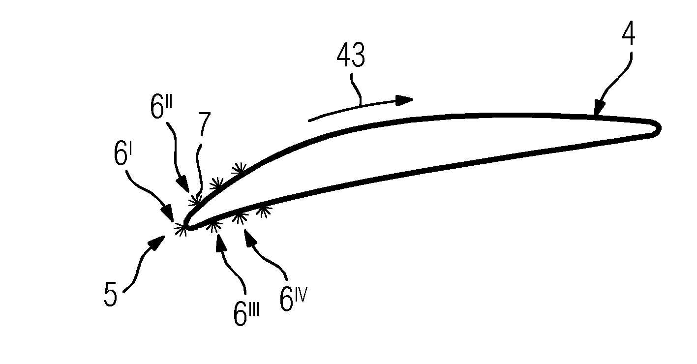
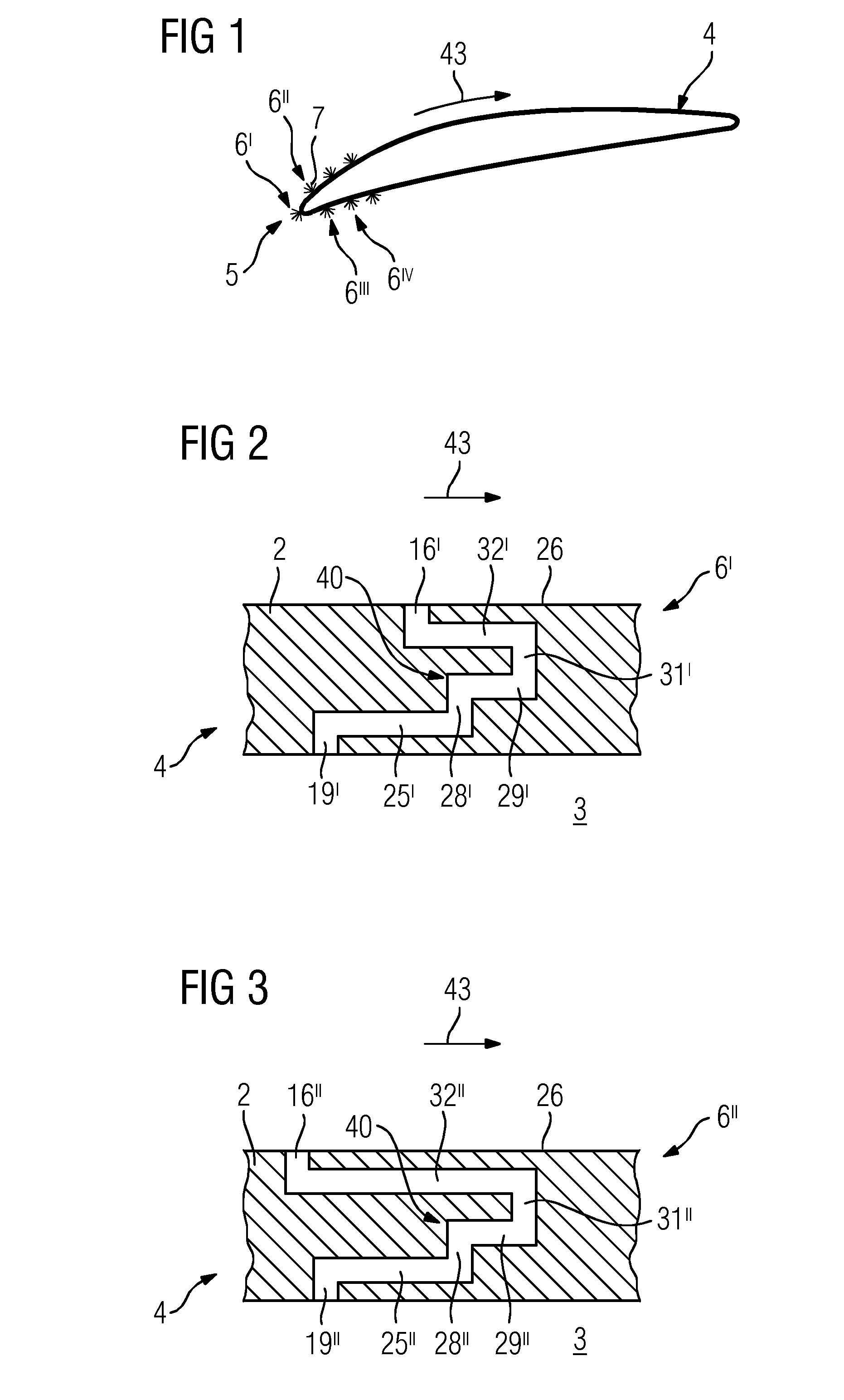
[0010]FIG. 1 shows a cross section of a blade airfoil, in particular of a compressor blade 4, which, in particular at its leading edge or incident flow region 5 and downstream therefrom on the suction face and / or pressure face, has a plurality of nozzles 6, 6I, 6II, . . . , out of which a fluid 7, in particular water, exits.

[0011]This is used for wet compression when operating a gas turbine 100 (FIG. 13).

[0012]The suction and pressure faces can feature the same number or different numbers of nozzles 6, 6I, 6ii. . .

[0013]In particular, a nozzle 6, 6I, . . . is present in the leading edge 5.

[0014]Perpendicular to the plane of the drawing, more nozzles 6, 6I, . . . can be present at the leading edge 5 and / or on the suction face or pressure face.

[0015]The compressor blade 4 usually has, inside it, a hollow space 3 which is surrounded by walls 2 and by means of which the fluid can be fed to the nozzle ...


PUM


Abstract

A compressor blade having at least one nozzle for ejecting fluid, in particular for ejecting water, is provided. The at least one nozzle is produced as a laminar structure in which, in particular, individual layers such as metal sheets are laid on top of each other, and has differently orientated channel sections of a channel between an inlet and an outlet, wherein the metal sheets have cutouts corresponding to the channel sections. The nozzle geometry makes it possible to prevent the formation of droplets as water exits a compressor blade.

Description

CROSS REFERENCE TO RELATED APPLICATIONS[0001]This application is the US National Stage of International Application No. PCT / EP2012 / 063816 filed Jul. 13, 2012, and claims the benefit thereof. The International Application claims the benefit of German Application No. DE 102011079195.7 filed Jul. 14, 2011. All of the applications are incorporated by reference herein in their entirety.FIELD OF INVENTION[0002]The invention relates to a compressor blade having nozzles for injecting a fluid into the compressor.BACKGROUND OF INVENTION[0003]Gas turbines can be operated with what is termed wet compression, in which a fluid is injected, inside the compressor of the gas turbine, into the air flowing through the compressor and which is to be compressed therein.[0004]However, this gives rise to the danger of drop formation, which can in turn lead to drop impingement erosion and thus to damage to downstream blades.SUMMARY OF INVENTION[0005]It is an object of the invention therefore to solve the ab...

Claims


Application Information

Patent Timeline
IPC IPC(8): F01D5/18
CPCF02C7/1435F01D5/18
Inventor WERNER, KLAUS
Owner SIEMENS AG
Learn More