Infected dental implant cleaning technique
- Summary
- Abstract
- Description
- Claims
- Application Information
AI Technical Summary
Benefits of technology
Problems solved by technology
Method used
Image
Examples
first embodiment
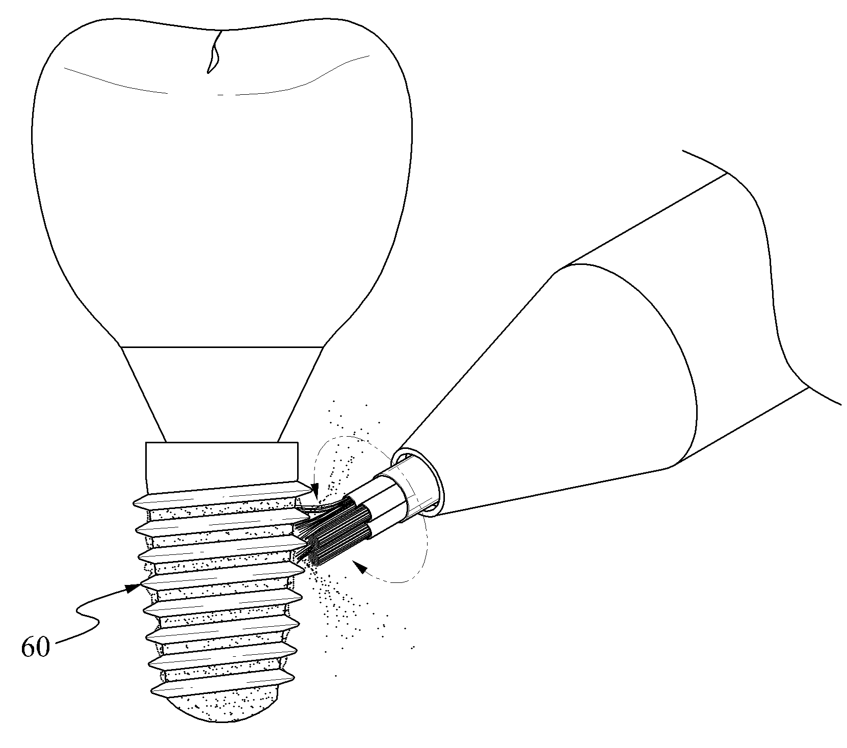
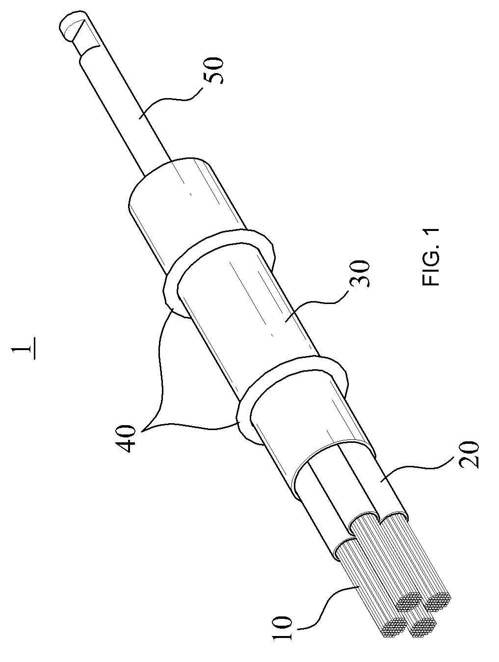
[0027]Referring to FIGS. 1 and 2, a dental implant cleaning apparatus 1 according to the present invention may include a wire bundle 10, a tube 20, a driver body 30, an O-ring 40, and a shaft 50.
[0028]The wire bundle 10 may include a plurality of wires. The wires may be formed of bendy and flexible materials, or metal materials having elasticity. The wires may desirably be formed of shape-memory alloys, such as nickel-titanium (Ni—Ti) alloys, and the like.
[0029]The wire bundle 10 may be in direct contact with a dental implant, and may scrap food scraps, pollutants, and the like that exist in an outer circumference of a dental implant 60. Additionally, the wires may each have a diameter of about 1 nm (0.05 mm˜0.1 mm), and may be very small and long. Accordingly, the wires may easily remove remnants that deeply exist in a screw thread of the dental implant 60, for example.
[0030]In addition, since the wire bundle 10 is formed of bendy and flexible materials, the outer circumference of ...
third embodiment
[0061]Referring to FIGS. 7 through 9, a dental implant cleaning apparatus 3 according to the present invention may include a driver 100, a cover 200, a brush 300, and an O-ring 400.
[0062]The driver 100 may be connected to a motor and the like, to receive provided rotatory power and to rotate the brush 300, or may be connected to an ultrasonic generator and the like, to receive provided vibration and to vibrate the brush 300.
[0063]The driver 100 may include a shaft 110, a driver body portion 120, and an implant receiving portion 130.
[0064]The shaft 110 may have a longitudinally extended cylindrical shape. The shaft 110 may provide a center of rotation of the driver 100, or may provide a center of vibration. The shaft 110 may be connected to a driving source, such as a motor and the like, and may receive driving force from the driving source.
[0065]The driver body portion 120 may be connected to the shaft 110, or may be formed integrally with the shaft 110. The driver body portion 120 ...
fourth embodiment
[0089]FIG. 11 is an exploded perspective view of a dental implant cleaning apparatus according to the present invention.
[0090]The dental implant cleaning apparatus according to the fourth embodiment of the present invention may merely differ in a connection method and a structure of a brush from the dental implant cleaning apparatus according to the third embodiment of the present invention, and accordingly description of the other parts will be quoted from the third embodiment.
[0091]Referring to FIG. 11, a brush 500 according to the fourth embodiment of the present invention may include a brush body portion 510, and a wire bundle 520. The brush body portion 510 may enclose a part of the wire bundle 520. The brush body portion 510 may be formed in a cylindrical shape, and a space, into which the wire bundle 100 is to be inserted, may be formed in the brush body portion 510.
[0092]The brush body portion 510 may collect wires in the wire bundle 520 to prevent the wires from being dispe...
PUM
 Abstract
Description
Claims
Application Information
 - R&D
- Intellectual Property
- Life Sciences
- Materials
- Tech Scout
- Unparalleled Data Quality
- Higher Quality Content
- 60% Fewer Hallucinations
Browse by: Latest US Patents, China's latest patents, Technical Efficacy Thesaurus, Application Domain, Technology Topic, Popular Technical Reports.
© 2025 PatSnap. All rights reserved.Legal|Privacy policy|Modern Slavery Act Transparency Statement|Sitemap|About US| Contact US: help@patsnap.com


