
Muzzleloader bullet system

a bullet system and muzzleloader technology, applied in the field of muzzleloader bullet systems, can solve the problems of creating a substantial safety risk, complicated determination, unique loading process of muzzleloaders, etc., to improve the overall ballistic or firing characteristics of the bullet, reduce the drag of the jacketed bullet in flight, and improve the overall ballistic characteristics of the bullet

Active Publication Date: 2014-05-15
FEDERAL CARTRIDGE
View PDF9 Cites 35 Cited by
  • Summary
  • Abstract
  • Description
  • Claims
  • Application Information

AI Technical Summary

Benefits of technology

The patent text describes a new design for a bullet that has a tail portion that can move in the well cavity of the cup between an extended position and a retracted position. The tail portion is designed to minimize friction between the bullet and the barrel, allowing for easy loading and tactile feedback when the bullet is seated against the propellant charge. Additionally, the patent text describes a component that can be compressed and seated into the bullet body to create a shorter projectile that is more efficient in its axial movement through the barrel.

Problems solved by technology

The loading process of muzzleloaders creates issues unique to muzzleloaders.
The friction between the bullet and the barrel can complicate the determination as to whether the bullet has been pushed far enough down the barrel during loading and is properly seated against the propellant charge.
The relative position of the bullet to the propellant charge changes the pressurization of the barrel behind the bullet from the ignited propellant gases impacting the ballistic performance and potentially creating a substantial safety risk.
While the sabot substantially improves the ballistic performance of the muzzleloader, the polymer sabot can be damaged or deformed by passing through the barrel and engaging the rifling twice.
The deformation of the sabot or damage to the sabot can cause the sabot to release the bullet prematurely or impart a wobble to the bullet.
A similar concern with muzzleloaders is that the slower burning propellant required by muzzleloaders often foul the barrel with unconsumed residue requiring frequent cleaning of the barrel.
The fouling often occurs so quickly that the barrel must be cleaned after every shot.
The fouling can also interfere with the operation the sabot causing the sabot to begin to unfurl from the bullet prematurely within the barrel or break up within the barrel.
In addition to contributing the fouling of the barrel, the deformation or damage to the sabot can impart wobble into the bullet or otherwise impact the ballistic performance of the bullet.
An additional complication is that the actual inner diameter of the barrel for given caliber can vary from manufacturer to manufacturer.
Although the variance is relatively small, the variance in tolerances between the inner diameter of the barrel and the outer diameter of the sabot can result in substantially increased friction between the cupped bullet and the barrel, which can cause the bullet to become stuck within the barrel during firing or loading.
Similarly, an improper fit between the barrel and an undersized sabot can create an inefficient seal between the sabot and the barrel allowing gases to escape around the bullet during firing.
Accordingly, if the sabot-bullet pairing is not properly selected, the effectiveness of the muzzleloader can be substantially impacted.
Although this approach is relatively easy to implement and widely used, the visual indicator approach detracts from the primary advantages of muzzleloaders.
As the visual indicator approach is set based on a particular propellant charge and bullet combination, a variation in the propellant charge that changes the dimensions of the propellant charge can render the visual indicator at best useless or at worse a safety risk giving a false appearance of a properly seated bullet.
As discussed above, the fouling can interfere with the safe operation of the muzzleloader as well as the ballistic performance of the bullet.
In a hunting situation where the muzzleloader may be fired several times to unload the muzzleloader for transport, the barrel may require cleaning, which can be difficult in the field.
While the approach is effective in safely separating the propellant charge from the bullet, a common problem with removable breech plugs is seizing of the breech plug within the barrel.
The rapid temperature changes during firing as well as the corrosive nature of many of the propellants can result in seizing of the corresponding threads of the breech plug and the barrel.
If not carefully maintained, the breech plug will become difficult to remove to efficiently unload the muzzleloader.
A related concern is that the performance of the hygroscopic propellant itself can be easily and often detrimentally impacted by the environmental conditions in which the propellant is stored.
The sensitivity of the propellant can often result in “hang fires” where the ignition of the propellant charge is delayed or the propellant charge fails to ignite altogether.
Hang fires are frequent occurrences and create a substantial risk for the user.
The unloading process through the muzzle of the muzzleloader is particularly dangerous in hang fire situations as the propellant charge may ignite during the actual unloading process.
Similarly, unloading through a breech plug can similarly be dangerous as the propellant charge may ignite as the breech plug is removed.
While measures are often used to provide a constant quantity of propellant for each propellant charge, the measures can be difficult to use in the field or in low light situation when hunting often occurs.
As with the measure, loading the appropriate number of pellets can be challenging in the field or in low light situations.
However, tightly fitting the bullet to the barrel can make properly seating of the bullet against the propellant charge and determining the position of the bullet within the barrel during loading difficult.

Method used


Image

  • Muzzleloader bullet system
  • Muzzleloader bullet system
  • Muzzleloader bullet system

Examples


Embodiment Construction

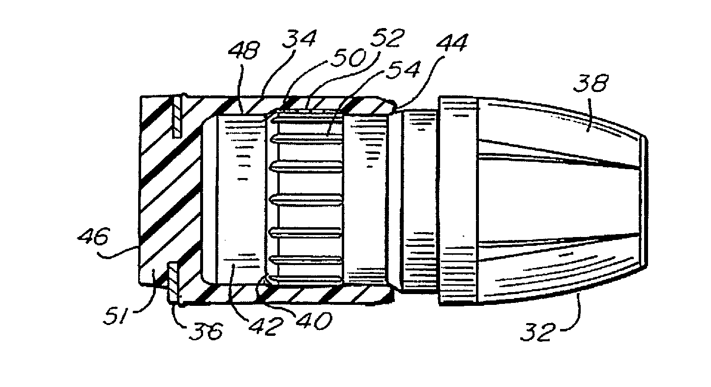
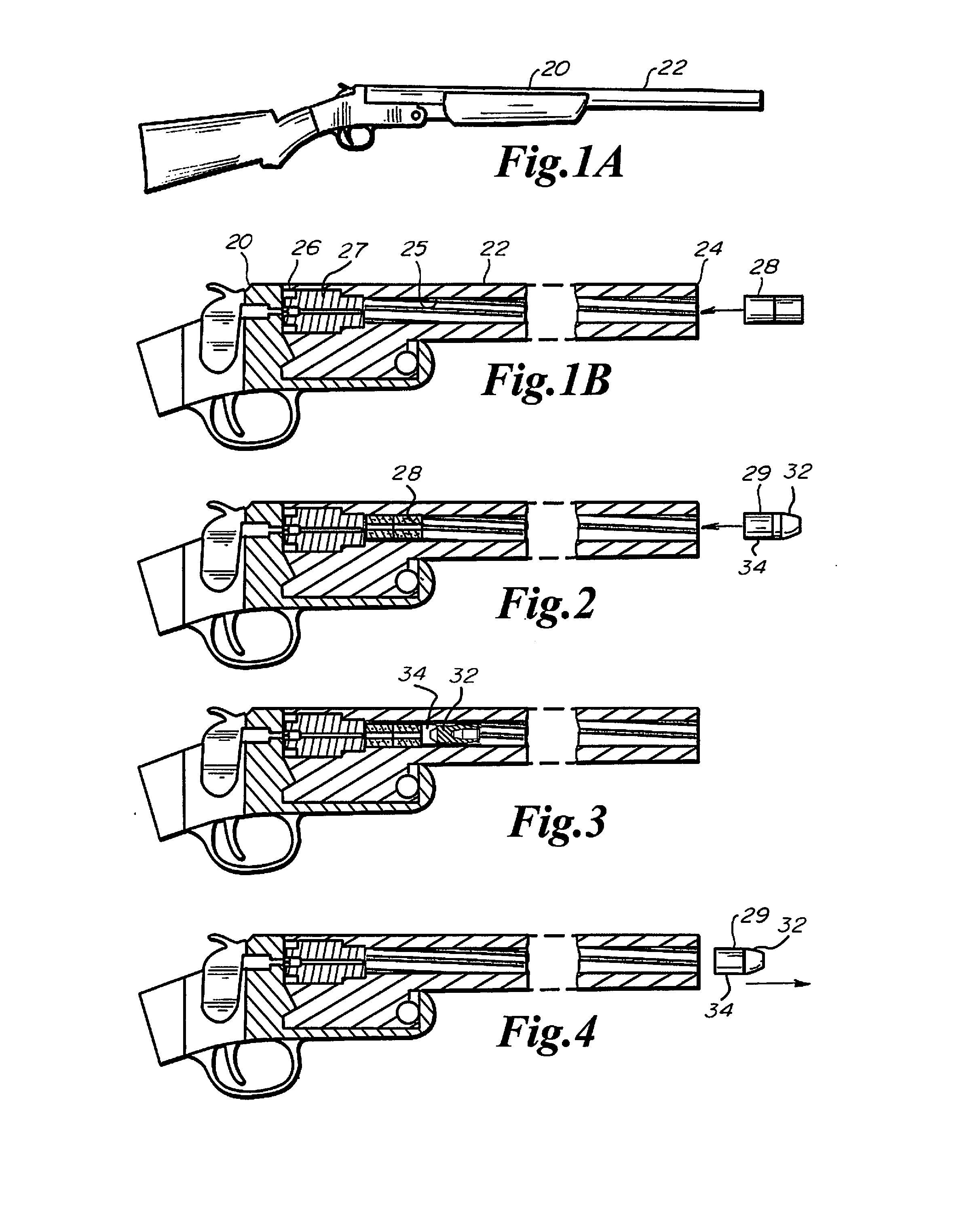
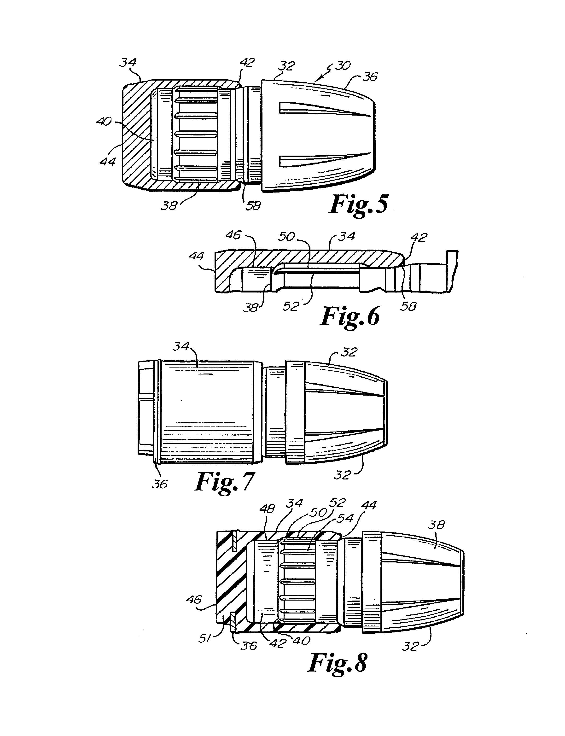
[0132]As depicted in FIGS. 1A-5, a muzzleloader 20, for use with the present invention, generally comprises a barrel 22 having a muzzle 24, a breech end 26 with a breech plug 27 therein. The barrel 22 can comprise smooth bore or a rifled bore 25 as depicted in FIG. 1. As depicted in FIGS. 2-4, the muzzleloader 20 may be conventionally loaded by loading a propellant charge 28 through the muzzle 24 of the barrel 22 and pushing the propellant charge 28 toward the breech end 26 of the barrel 22. A projectile 29, with a bullet, and a shiftable cup 34 on the tail of the bullet, according to the invention is positioned in the muzzle 24 of the barrel 22 before being pushed down the barrel 22 with the ramrod until the bullet is seated against the propellant charge 28 As shown in FIG. 3. The muzzleloader is then ready to be fired and the is in an axially elongated state. FIG. 4 illustrates the muzzleloader after the bullet has been fired, the bullet in an axially retracted or compressed state...


PUM


Abstract

A bullet system including a bullet body with a tail portion engaged with a polymer cup that provides enhanced engagement of the barrel upon firing. The bullet system may have a radial retracted state that corresponds to an elongated axial state of the bullet system that allows the cupped bullet to be fed down the barrel at a reduced diameter with reduced engagement with the barrel. The radial expansion of the bullet system occurs upon axial length reduction of the bullet system by axial compression. The axial compression can occur upon firing of the propellant or when loading with the ramrod. The bullet system can provide a tactile seat force indicator tip insert within the tip of the bullet body that provides a tactile sensation when the bullet is properly seated against the propellant charge. A cutting edge may be provided for scraping the barrel upon insertion of the bullet.

Description

PRIORITY CLAIM[0001]This application claims priority to U.S. Provisional Application No. 61 / 707,520, filed Sep. 28, 2012, U.S. Provisional Application No. 61 / 852,480, filed Mar. 15, 2013, and U.S. Provisional Application No. 61 / 802,264, filed Mar. 15, 2013, each of which is hereby fully incorporated herein by reference.FIELD OF THE INVENTION[0002]The present invention is directed to a bullet system suitable for muzzleloaders that improves the sealing of the bullet against the barrel during loading, and improves loading and shot accuracy. Specifically, the present invention is directed to a bullet having a radially deformable polymer component that may expand during seating or firing of the bullet to engage the barrel and to seal the bullet against the barrel and provide engravable material engagable by the rifling of the barrel.BACKGROUND OF THE INVENTION[0003]Muzzleloaders are a class of firearms in which the propellant charge and bullet are separately loaded into the barrel immedi...

Claims


Application Information

Patent Timeline
Patent Type & Authority Applications(United States)
IPC IPC(8): F42B30/02F42B14/00F42B12/76
CPCF42B30/02F42B14/00F42B12/76F42B5/38F42B8/04F41A3/58F41A9/375F41C7/11F41C9/085F41C9/08F41A3/00F41C7/00
Inventor PETERSON, BRYAN P.GOODLIN, DREW L.CARLSON, ERIK K.HEAD, LAWRENCE P.SWENSON, JOHN W.JONES, SHARON
Owner FEDERAL CARTRIDGE
Learn More