
Adjustment simulation method for energy consumption

Active Publication Date: 2014-05-08
CENERGISTIC LLC
View PDF4 Cites 80 Cited by
  • Summary
  • Abstract
  • Description
  • Claims
  • Application Information

AI Technical Summary

Benefits of technology

The present invention relates to a system and method for assessing, calibrating, and modifying the energy usage profile of a building to impact energy consumption by the building and occupants. The invention takes into account a large number of variables involved in energy usage, such as occupant behavior and equipment efficiency, to provide a more accurate assessment and calibration of the energy usage profile. The invention can also incorporate historical data and real-time feedback to improve energy consumption and decision-making. The technical effects of the invention include improved energy efficiency, reduced energy costs, and improved building performance.

Problems solved by technology

The baseline energy costs may be inaccurate due to unverified and unreported occupant and systems behavior which is not directly discoverable.
Furthermore, there are a large number of variables involved in the modeling of energy consumption such as occupant behavioral factors and unknown equipment efficiencies that feed inaccuracy of the results and lead to poor decision making.
Calibration of the baseline energy usage profile to historical energy usage is possible; however, calibration methods are not an exact science due to the large number of variables involved.
Subbarao utilizes the energy simulator DOE-2 which requires complex evaluation of a large number of inputs and outputs and is not suitable for providing rapid feedback.
Carr does not disclose a calibration process for energy-usage.
The drawback of Barclay et al. is that the disclosed method requires a wide variety of training data sets to predict energy savings accurately.
Fitch et al. requires complex evaluation of a large number of inputs and outputs.

Method used


Image

  • Adjustment simulation method for energy consumption
  • Adjustment simulation method for energy consumption
  • Adjustment simulation method for energy consumption

Examples


Embodiment Construction

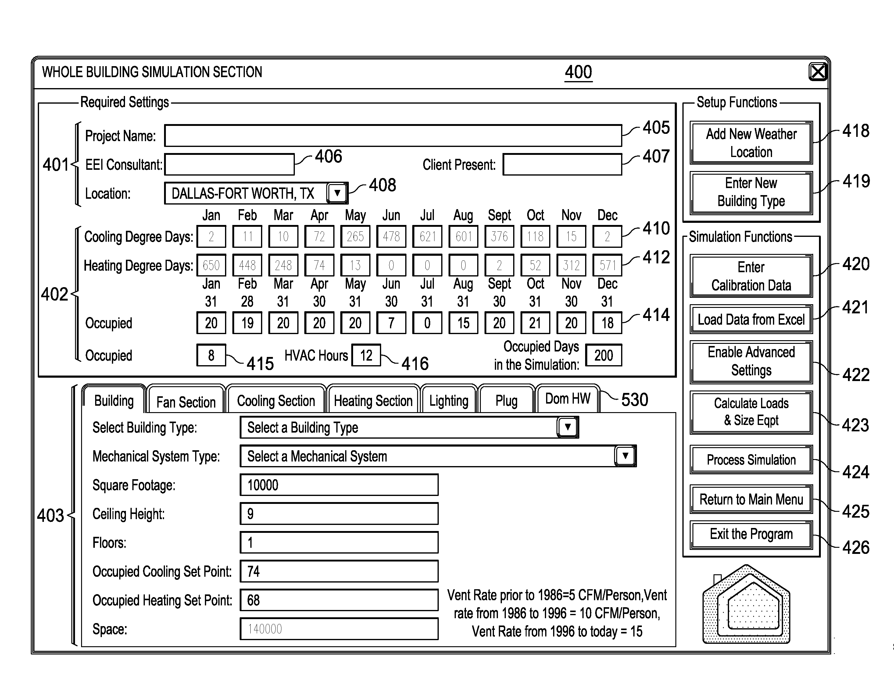
[0037]The system and methods described are implemented using digital computer systems. In one aspect of the present disclosure, the systems and methods are implemented on a digital computer having a processor for executing the methods embodied within a set of program instructions. The program instructions are stored in an electronic memory and in digital storage media connected to the digital computer. The digital computer includes a user interface system including a display device and a keying device. The digital storage media can include a compact disc, a hard drive, a flash drive or any other form of portable or non-portable persistent storage suitable for electronically storing program instructions.

[0038]In a preferred embodiment, the set of program instructions are implemented within a spreadsheet program on the digital computer, for example, a set of macros and Visual Basic code in a Microsoft ExcelTM spreadsheet. However, implementation of the methods of the present disclosur...


PUM


Abstract

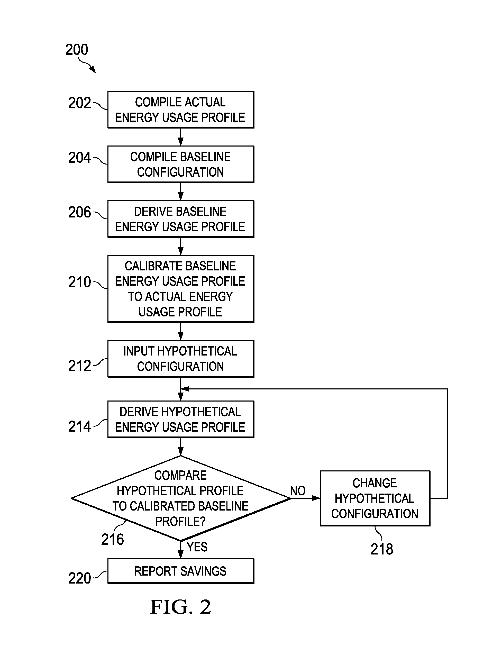
A method for analyzing energy savings for a building is provided. The method includes receiving a historical energy usage and a weather data for a building, a set of operations parameters describing building operations and a set of building system parameters describing building systems. A baseline configuration is submitted to a first energy consumption simulation to determine a baseline energy usage profile. A calibrated configuration is determined from the baseline configuration and the historical energy usage. The calibrated configuration is submitted to a second energy consumption simulation to determine a calibrated energy usage profile. A hypothetical configuration is determined from the calibrated configuration and a set of energy improvement measures. The hypothetical configuration is submitted to a third energy consumption simulation to determine a hypothetical energy usage profile and report. The set of energy improvement measures are approved and implemented based on the hypothetical energy usage profile.

Description

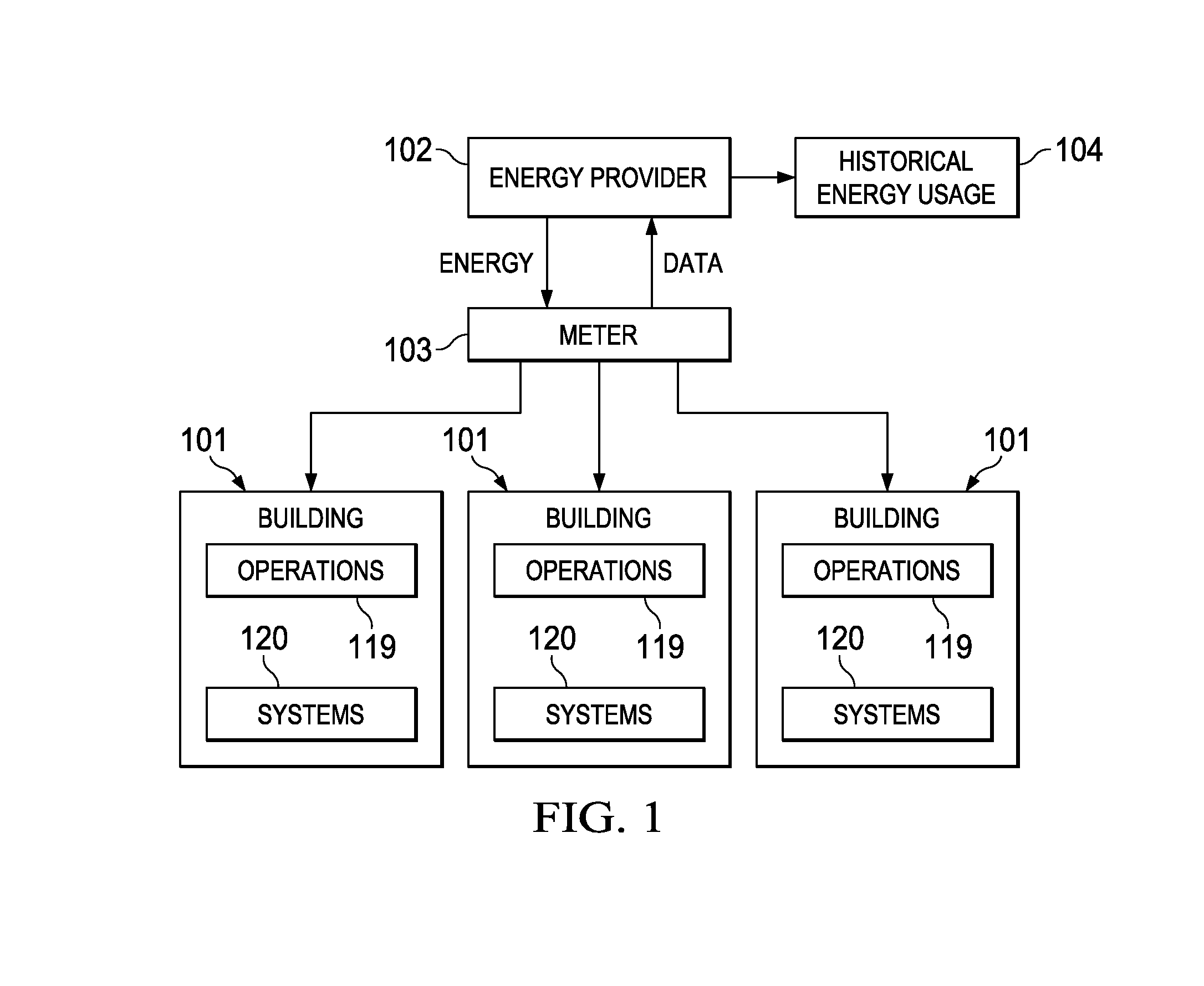
FIELD OF THE INVENTION[0001]The present invention relates to assessment, calibration and modification of the energy usage profile for a building to impact energy consumption by the building and occupants.BACKGROUND OF THE INVENTION[0002]Control of energy costs is a high priority with businesses and governments. The assessment of a baseline energy usage profile for a building as related to mechanical systems consumption due to heating and cooling loads is fairly well understood according to building science principles. The baseline energy costs may be inaccurate due to unverified and unreported occupant and systems behavior which is not directly discoverable. Furthermore, there are a large number of variables involved in the modeling of energy consumption such as occupant behavioral factors and unknown equipment efficiencies that feed inaccuracy of the results and lead to poor decision making. Calibration of the baseline energy usage profile to historical energy usage is possible; ho...

Claims


Application Information

Patent Timeline
IPC IPC(8): G06F17/50G06G7/48
CPCG06Q30/0201G06Q30/0205G06Q30/0206G06F30/13G06F30/367G06F30/20Y02T10/82
Inventor SONS, BRYANBULLOCK, JACK
Owner CENERGISTIC LLC
Learn More