
Washer assembly and joint monitoring system employing the same

a technology of joint monitoring and washer assembly, which is applied in the direction of force/torque/work measurement apparatus, liquid/fluent solid measurement, instruments, etc., can solve the problems of consuming a technician's time, reducing the conductivity of electrical joints, and consuming a large amount of technician's time to verify whether electrical joints are properly tightened

Active Publication Date: 2014-05-08
EATON INTELLIGENT POWER LTD
View PDF6 Cites 76 Cited by
  • Summary
  • Abstract
  • Description
  • Claims
  • Application Information

AI Technical Summary

Benefits of technology

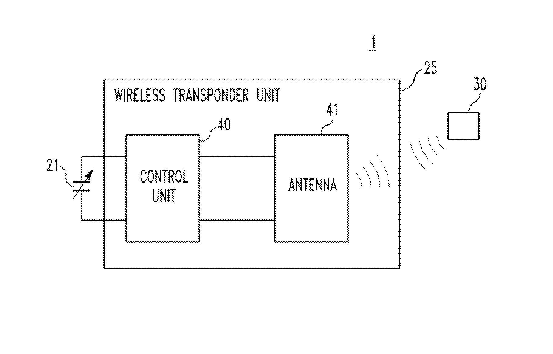
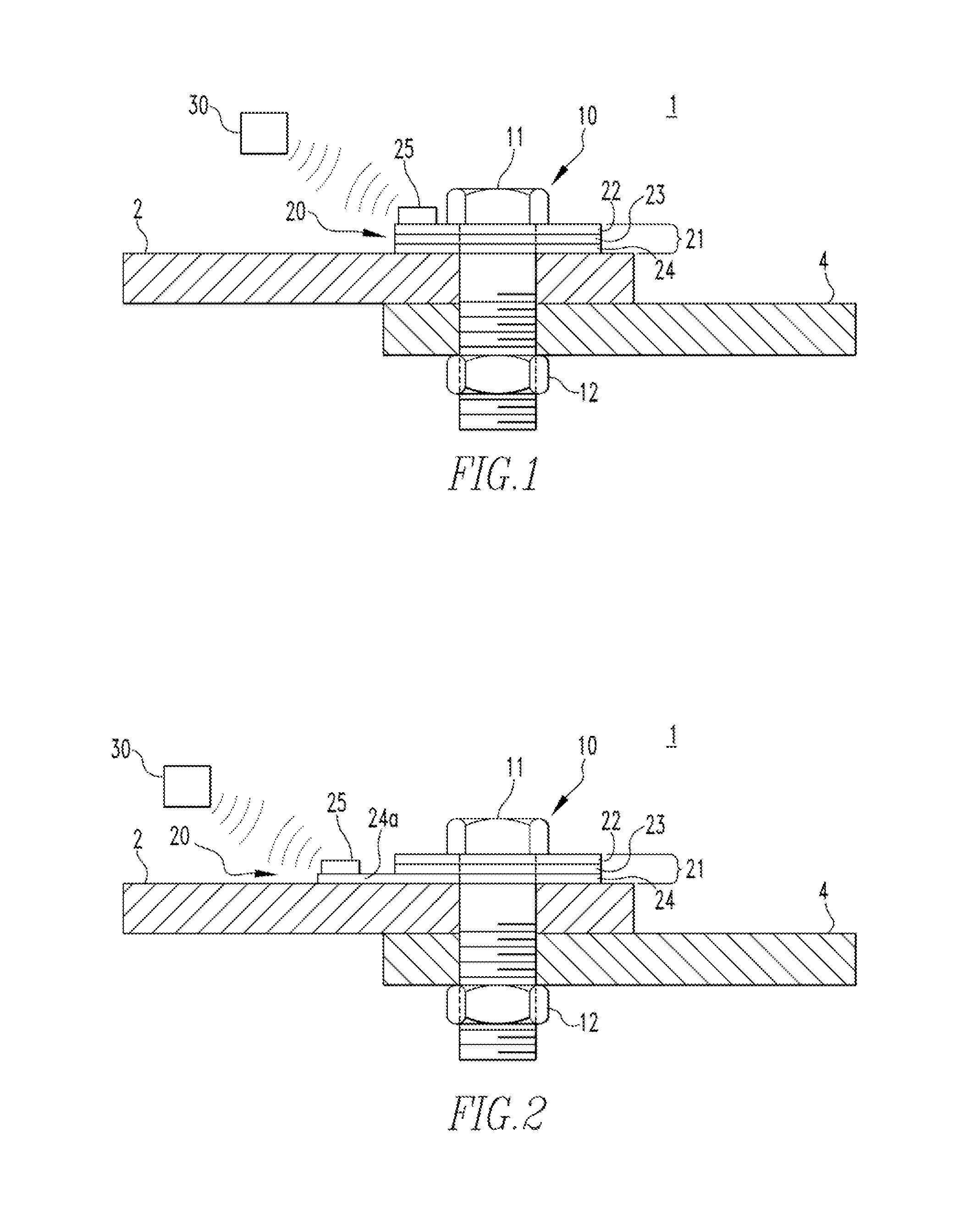
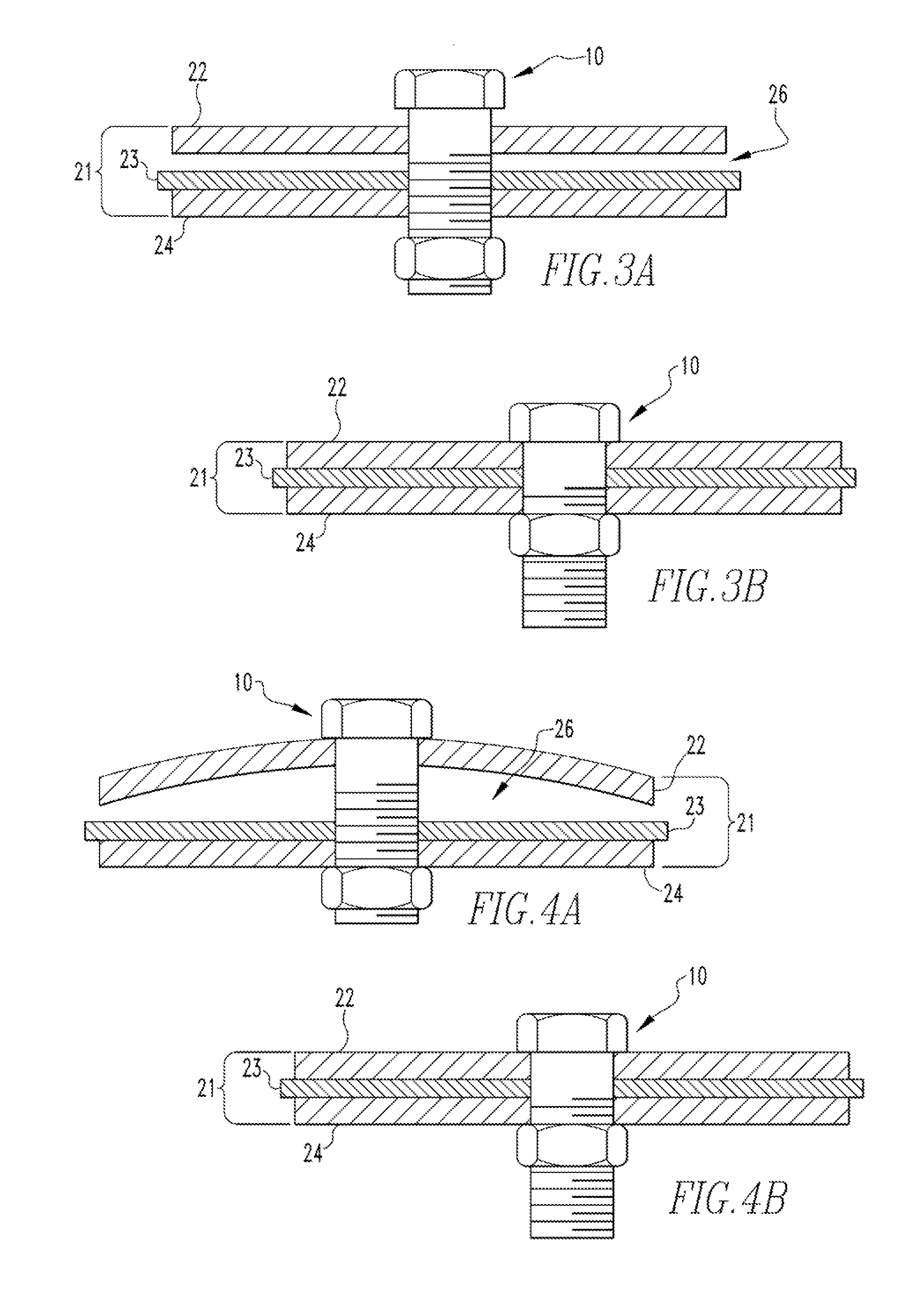
The patent text describes a washer assembly and a joint monitoring system that use a variable capacitor and a wireless transponder unit to monitor the force applied by a fastener or the joint formed by two members. The washer assembly includes a first conductive portion, a second conductive portion, and an insulating portion that form a variable capacitor, and the wireless transponder unit includes a control unit and an antenna that connect to the variable capacitor. The control unit senses the capacitance of the variable capacitor and sends the information to a wireless reader unit. This technology allows for accurate monitoring of fasteners and joints.

Problems solved by technology

A loosening of the fastener, and therefore a loosening of the electrical joint, reduces the conductivity of the electrical joint and can cause additional problems such as overheating.
However, verifying, whether electrical joints are properly tightened can consume a technician's time.
In particular, when an electrical system includes numerous electrical joints, or if it is difficult to reach electrical joints, a large amount of a technician's time can be taken verifying whether electrical joints are properly tightened.
Also, the electrical joint may be energized, thus exposing the technician to a hazardous condition.

Method used


Image

  • Washer assembly and joint monitoring system employing the same
  • Washer assembly and joint monitoring system employing the same
  • Washer assembly and joint monitoring system employing the same

Examples


Embodiment Construction

.

[0017]Directional phrases used herein, such as, for example, left right, front, back, top, bottom and derivatives thereof, relate to the orientation of the elements shown in the drawings and are not limiting upon the claims unless expressly recited therein.

[0018]As employed herein, the term “fastener” refers to any suitable connecting or tightening mechanism expressly including, but not limited to, screws, bolts and the combinations of bolts and nuts (e.g., without limitation, lock nuts) and bolts, washers and nuts.

[0019]As employed herein, the statement that two or more parts are “coupled” together shall mean that the parts are joined together either directly or joined through one or more intermediate parts.

[0020]As employed herein, the term “number” shall mean one or an integer greater than one (i.e., a plurality),

[0021]As employed herein, the term “washer” refers to any member structured to be placed between a portion of fastener and an item that is being fastened.

[0022]As emplo...


PUM

PropertyMeasurementUnit
capacitanceaaaaaaaaaa
conductiveaaaaaaaaaa
resonant frequencyaaaaaaaaaa

Abstract

A washer assembly is for use with a fastener. The washer assembly includes a first conductive portion, a second conductive portion, and an insulating portion disposed between the first conductive portion and the second conductive portion. The first conductive portion, the second conductive portion, and the insulating portion form a variable capacitor having a capacitance based on an amount of force applied thereto by the fastener. A wireless transponder unit includes a control unit electrically connected to the variable capacitor and an antenna electrically connected to the control unit. The control unit is configured to sense the capacitance of the variable capacitor, to generate information representing the capacitance, and to output the information to a wireless reader unit via the antenna.

Description

BACKGROUND[0001]1. Field[0002]The disclosed concept relates generally to joint tightness monitoring and more particularly, to electrical joint tightness monitoring.[0003]2. Background Information[0004]One typical type of electrical joint is formed by securing two conductors together with a fastener. The electrical performance of the electrical joint, and in particular, the conductivity of the electrical joint, depends partially on the fastener being properly tightened. A loosening of the fastener, and therefore a loosening of the electrical joint, reduces the conductivity of the electrical joint and can cause additional problems such as overheating.[0005]Due to the aforementioned problems, it is desirable to determine whether electrical joints are properly tightened. However, verifying, whether electrical joints are properly tightened can consume a technician's time. In particular, when an electrical system includes numerous electrical joints, or if it is difficult to reach electric...

Claims


Application Information

Patent Timeline
Patent Type & Authority Applications(United States)
IPC IPC(8): G01N27/22G01R27/26G06F19/00
CPCG01L5/243G01F23/263G01L1/142G01M13/005
Inventor SHEA, JOHN, J.
Owner EATON INTELLIGENT POWER LTD
Learn More