
Straight tube luminaire

Inactive Publication Date: 2014-05-08
SHIMYAU
View PDF5 Cites 4 Cited by
  • Summary
  • Abstract
  • Description
  • Claims
  • Application Information

AI Technical Summary

Benefits of technology

The present invention provides a straight tube luminaire with a reflective plate and a rotatable connection terminals that can be set in different positions for energy saving and to prevent discomfort while attempting energy saving. The straight tube luminaire can be easily rotated to switch its lighting and to decrease the number of lit lights when attempting energy saving. The invention also includes holding parts and auxiliary members that can hold the straight tube luminaire in a fixed position and adjust its rotation. Additionally, the invention includes a distribution part that supplies current to the straight tube illumination sockets for easy and convenient power connection.

Problems solved by technology

According to differences between individuals, eye fatigue tends to occur and the LEDs do not offer a comfort in some cases.

Method used


Image

  • Straight tube luminaire
  • Straight tube luminaire
  • Straight tube luminaire

Examples


first embodiment

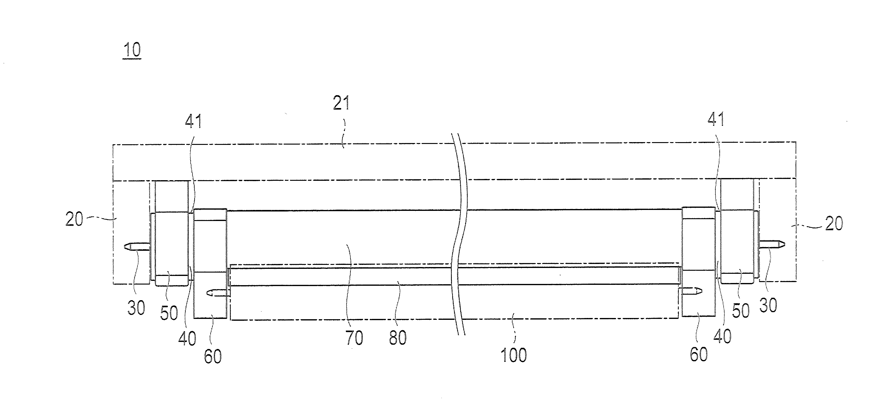
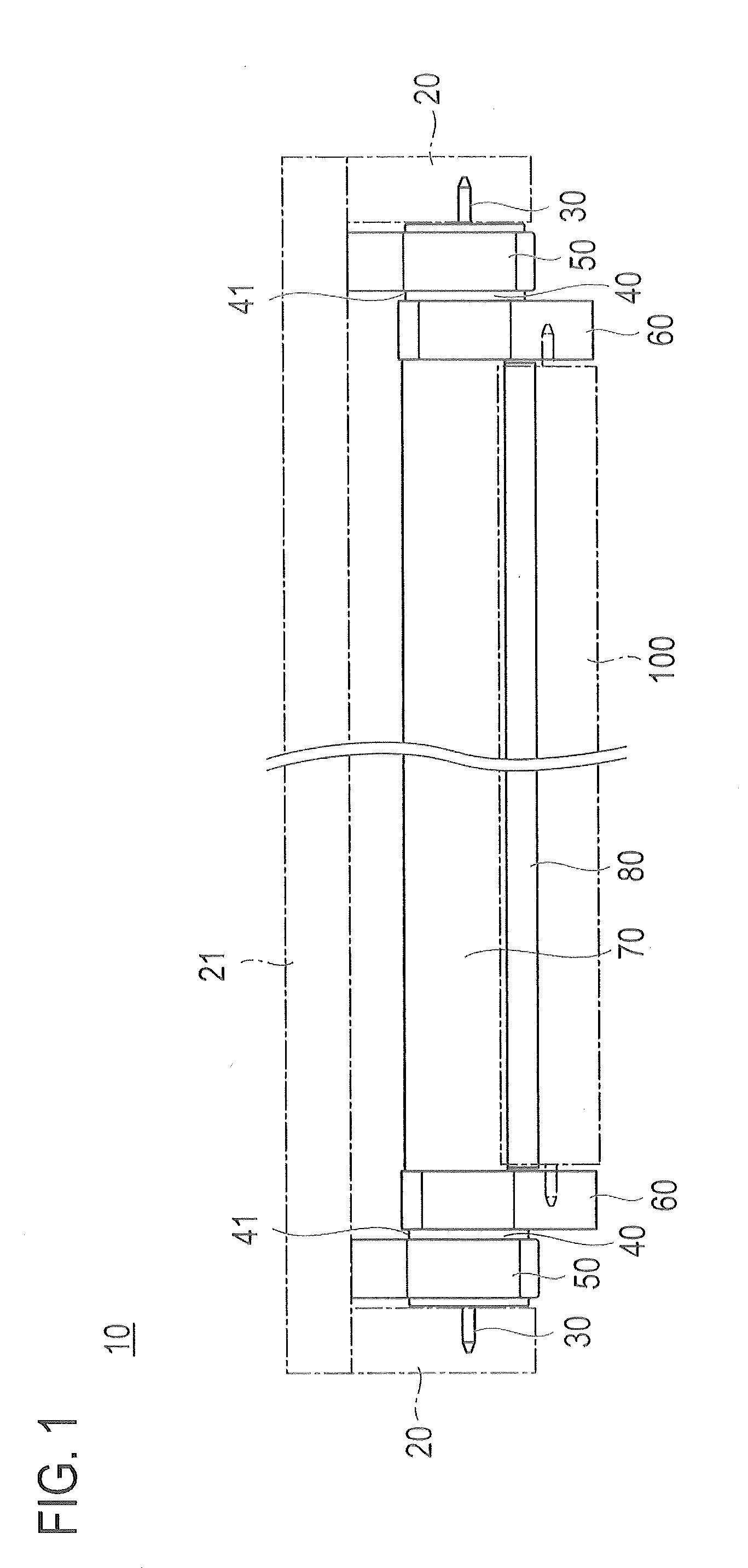
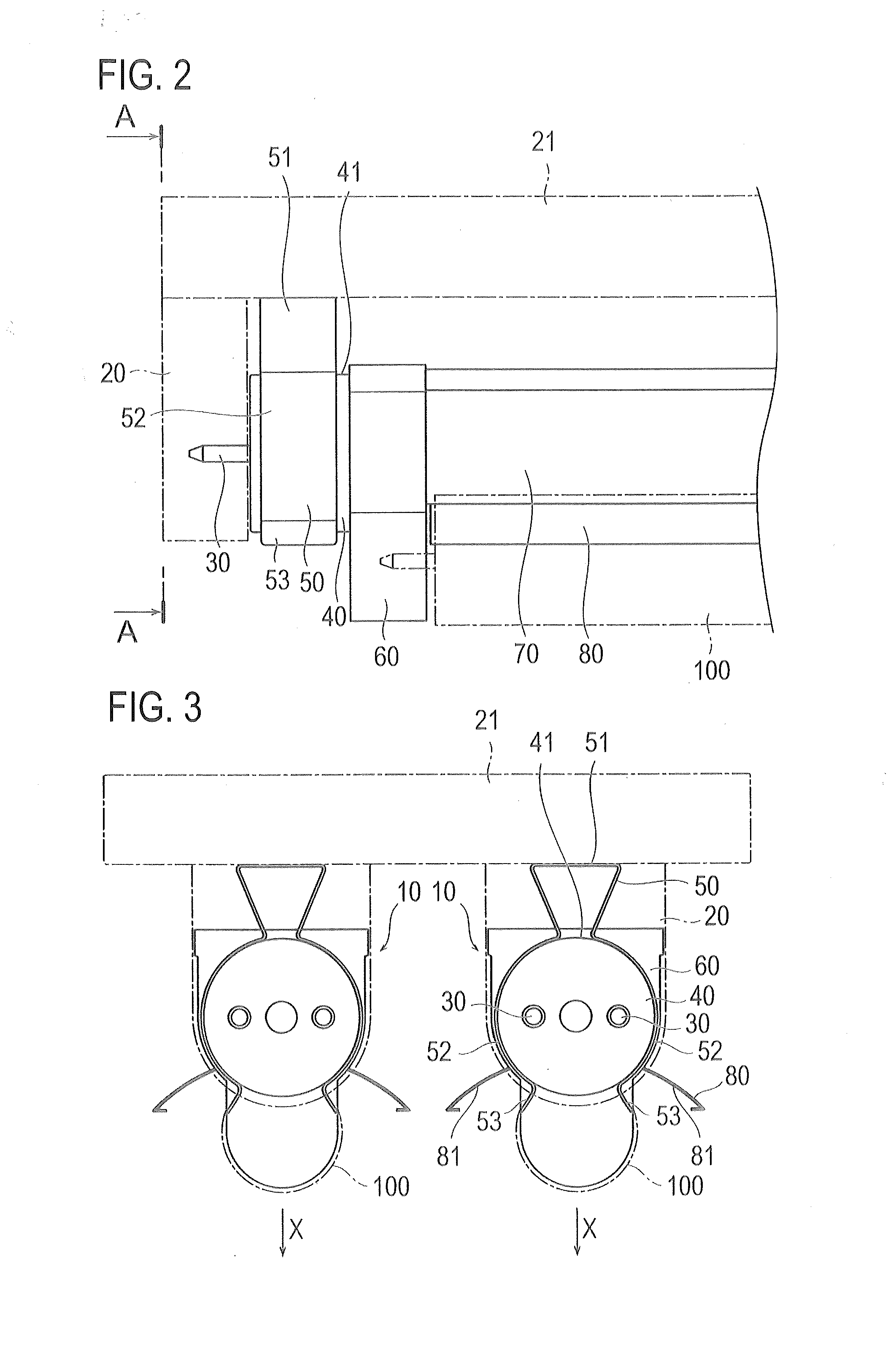
[0026]A straight tube luminaire 10 according to a first embodiment makes it possible to attach a T5 straight tube fluorescent lamp 100 (straight tube illuminating lamp), which is smaller in diameter and less in power dissipation than a T8 straight tube fluorescent lamp, by attaching it to rotary sockets 20 for attaching a T8 straight tube fluorescent lamp thereto.

[0027]As illustrated in FIG. 4, the rotary sockets 20 are fixed to a base 21 attached to a ceiling. As a two-lamp system in which two fluorescent lamps are lighted, two pairs of rotary sockets are provided on one base. Each rotary socket 20 includes a slit 22 into which two electrodes projecting from each of both ends of a fluorescent lamp are inserted, a circular groove 23 which makes the electrodes inserted into the slit 22 rotatable, and power supply terminals 24 which come in contact with the electrodes moved to predetermined rotational positions in the circular groove 23 and make it possible to apply a current to the e...

second embodiment

[0049]A straight tube luminaire 200 according to a second embodiment, as shown in FIG. 8 and FIG. 9, is a device that is removably attached to a base 270 on which sockets for attaching a straight tube illuminating lamp is removed, and that makes it possible to attach a straight tube illuminating lamp of different standards. Meanwhile, hereafter, an example in which, for example, push-in type sockets are removed from the base 270 for T8 straight tube fluorescent lamp and it is made possible to light the T5 straight tube fluorescent lamp 100 will be described.

[0050]The straight tube luminaire 200 includes two socket parts 210 to be connected to electrodes 101 (see FIG. 11) at both ends of the fluorescent lamp 100, and a distribution part 220 which supplies current to two socket parts 210 via cables 221 by connecting AC power supply 225.

[0051]The socket part 210 includes a socket housing 230. The socket housing 230 has mounting grooves 231, into which a linking convex part 271 (see FIG...


PUM


Abstract

A straight tube luminaire, detachably attached between one pair of opposed rotary sockets, includes one pair of connection terminals electrically connected to each of the pair of rotary sockets within a predetermined rotational range of the rotary sockets, one pair of straight tube illumination sockets electrically connected to the connection terminals and electrically connected to electrodes provided at both ends of a rectilinear fluorescent lamp, and a reflective plate extended between the pair of straight tube illumination sockets and attached to the straight tube illumination sockets to reflect light of the fluorescent lamp. The reflective plate and the straight tube illumination sockets are rotated as one body together with the connection terminals by inserting the connection terminals into the rotary sockets and rotating the rotary sockets.

Description

TECHNICAL FIELD[0001]The present invention relates to a straight tube luminaire that is attached to a socket for attaching a straight tube illuminating lamp and that is capable of lighting a straight tube illuminating lamp having a different size.BACKGROUND ART[0002]In recent years, importance of energy saving has increased from the viewpoint of global warming. In straight tube type illumination, energy saving is also demanded. For example, therefore, demand for LEDs which are less in power dissipation than fluorescent lamps is increasing.[0003]LEDs give a peculiar stimulus. According to differences between individuals, eye fatigue tends to occur and the LEDs do not offer a comfort in some cases. Accordingly, a technique of implementing mildness to eyes and energy saving by attaching a T5 straight tube fluorescent lamp (tube diameter: 15.5 mm), which is less in power dissipation than a T8 straight tube fluorescent lamp (tube diameter: 25.5 mm) used generally heretofore, to lamp sock...

Claims


Application Information

Patent Timeline
IPC IPC(8): F21V19/00F21V17/06F21V7/00
CPCF21V19/008F21V7/005F21V17/06F21S8/031F21V21/30F21Y2103/00F21Y2115/10H01R33/0854H05B41/02H05B45/3578Y02B20/30
Inventor MATSUURA, SADAAKI
Owner SHIMYAU
Learn More