Silicon carbide single crystal manufacturing apparatus

Active Publication Date: 2014-05-08
DENSO CORP
View PDF4 Cites 3 Cited by
  • Summary
  • Abstract
  • Description
  • Claims
  • Application Information

AI Technical Summary

Benefits of technology

The present invention aims to provide an improved apparatus for manufacturing SIC single crystals that can prevent clogging of the discharge path, maintain a high temperature at the growth surface of the crystal, and easily control the shape of the crystal. The technical effects of this apparatus include improved stability and control during the manufacturing process, resulting in higher quality and efficiency of the SIC single crystals produced.

Problems solved by technology

Accordingly, during growth of the SiC single crystal, clogging of the outlet due to attachment of SiC polycrystalline to the surroundings of the pedestal on which the seed crystal is disposed can be restricted, and the SiC single crystal can grow for a long time.
However, in a case where gas is discharged from the outlet above the seed crystal through a side surface of the seed crystal, as the SiC single crystal manufacturing apparatus described in the patent document 1, even when the inside diameter of the crucible is increased, an opening width of the discharge path is small, and it is difficult to stably prevent clogging.
This problem can be restricted when the inside diameter of the crucible is further increased.
Thus, it is difficult to keep a high temperature of a growth surface of the SiC single crystal and to control a shape of the SiC single crystal based on heat of the crucible and radiant heat.
Thus, it is difficult to further restrict clogging of the discharge path and to keep a high temperature of the growth surface of the SiC single crystal and to control the shape of the SiC single crystal more easily.

Method used


Image

  • Silicon carbide single crystal manufacturing apparatus
  • Silicon carbide single crystal manufacturing apparatus
  • Silicon carbide single crystal manufacturing apparatus

Examples


first embodiment

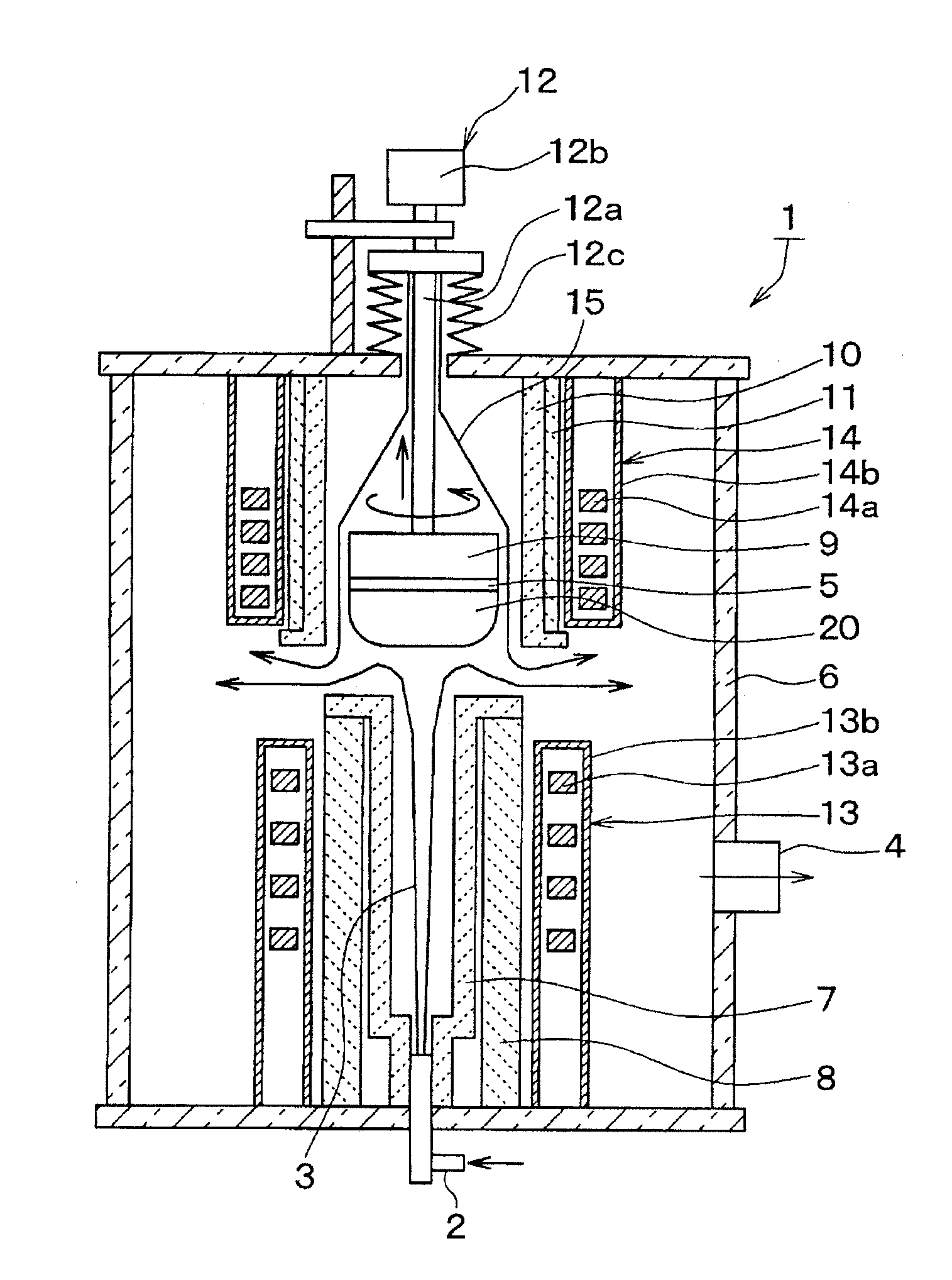
[0015]FIG. 1 shows a cross-sectional view of a SiC single crystal manufacturing apparatus 1 according to the present embodiment. A structure of the SiC single crystal manufacturing apparatus 1 will be described with reference to this figure.

[0016]In the SiC single crystal manufacturing apparatus 1 shown in FIG. 1, source gas 3 of SiC including Si and C (e.g., mixed gas of silane system gas, such as silane, as gas including silicon and hydrocarbon system gas, such as propane, as gas including carbon) is supplied with carrier gas through an inlet 2 disposed at a bottom and is discharged through an outlet 4 so that a SiC single crystal 20 is grown on a seed crystal 5 made of a SIC single crystal substrate disposed in the SiC single crystal manufacturing apparatus 1.

[0017]The SiC single crystal manufacturing apparatus 1 includes a vacuum chamber 6, a reaction chamber 7, a heat insulator 8, a pedestal 9, a guide 10, an outer peripheral heat insulator 11, a pull-up mechanism 12, and first...

second embodiment

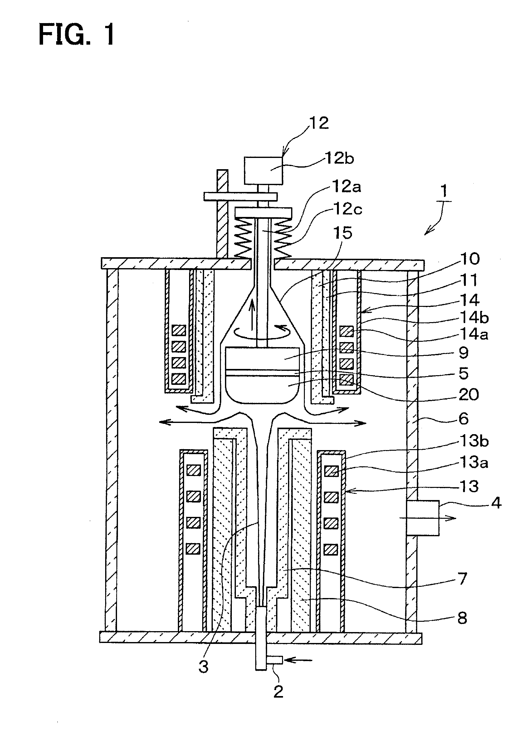
[0037]A second embodiment of the present disclosure will be described. In the present embodiment, the purge gas 15 is also introduced from a side adjacent to the reaction chamber 7 with respect to the first embodiment, and the other portions are similar to the first embodiment. Thus, only a portion different from the first embodiment will be described.

[0038]FIG. 2 is a cross-sectional view of a SiC single crystal manufacturing apparatus 1 according to the present embodiment. As shown in the figure, in the present embodiment, through holes 7a are provided at the end portion of the reaction chamber 7 adjacent to the guide 10, in particular, at the portion having the flange shape, the clearance is provided between the reaction chamber 7 and the heat insulator 8, and a inlet 16 of the purge gas 15 is provided on the bottom surface of the vacuum chamber 6. The through holes 7a are provided at regular interval in a circumferential direction centering on the central axis of the reaction ch...

third embodiment

[0040]A third embodiment of the present disclosure will be described. In the present embodiment, a protection structure of the vacuum chamber 6 is added with respect to the first embodiment, and the other portions are similar to the first embodiment. Thus, a portion different from the first embodiment will be described.

[0041]FIG. 3 is a cross-sectional view of the SiC single crystal manufacturing apparatus 1 according to the present embodiment. As shown in this figure, in the present embodiment, a shielding plate 17 is disposed so as to surround a periphery of the clearance between the reaction chamber 7 and the guide 10. The shielding plate 17 is made of, for example, graphite or graphite whose surface is coated with high melting-point metallic carbide, such as TaC (tantalum carbide). The shielding plate 17 is disposed at a position at a predetermined distance from the end portion of the guide 10 so as not to interrupt flow of the source gas 3 and the purge gas 15. Although it is n...


PUM

PropertyMeasurementUnit
Diameteraaaaaaaaaa
Electrical resistanceaaaaaaaaaa
Distanceaaaaaaaaaa

Abstract

A silicon carbide single crystal manufacturing apparatus includes a vacuum chamber, a pedestal on which a seed crystal is disposed, an inlet of source gas, a reaction chamber extending from a bottom surface of the vacuum chamber toward the pedestal, a first heating device disposed around an outer periphery of the reaction chamber, a second heating device disposed around an outer periphery of the pedestal, and an outlet disposed outside the first and second heating devices in the vacuum chamber. After the source gas supplied from the reaction chamber is supplied toward the pedestal, the source gas is let flow outward in a radial direction of the silicon carbide single crystal between the reaction chamber and the silicon carbide single crystal and is discharged through the outlet.

Description

CROSS REFERENCE TO RELATED APPLICATION[0001]This application is based on Japanese Patent Application No. 2011-165719 filed on Jul. 28, 2011, the disclosures of which are incorporated herein by reference.TECHNICAL FIELD[0002]The present disclosure relates to a silicon carbide (hereafter, referred to as SiC) single crystal manufacturing apparatus.BACKGROUND ART[0003]Conventionally, as a SiC single crystal manufacturing apparatus, a manufacturing apparatus having a structure described in the patent document 1 has been suggested. In the SiC single crystal manufacturing apparatus, a source gas inlet is provided below a seed crystal so as to introduce source gas from below the seed crystal. In addition, a gas outlet is provided above the seed crystal so as to discharge the rest of the source gas supplied to the seed crystal and carrier gas from above the seed crystal. Accordingly, new source gas is continuously supplied to the seed crystal to grow a SiC single crystal. In addition, in the...

Claims


Application Information

Patent Timeline
IPC IPC(8): C30B25/08C30B25/12C30B25/14C30B25/10
CPCC30B25/08C30B25/14C30B25/12C30B25/10C30B29/36
Inventor HARA, KAZUKUNI
Owner DENSO CORP
Why Eureka
Try Eureka