Image processing apparatus and method thereof
a technology of image processing and apparatus, applied in the field of image processing, can solve the problems of not having a technique for a measurement against the viewing density change, a reduction of toner consumption amount while maintaining and a problem of viewing density change, etc., to achieve the effect of enhancing the viewing density of an image and reducing the consumption amount of color materials
- Summary
- Abstract
- Description
- Claims
- Application Information
AI Technical Summary
Benefits of technology
Problems solved by technology
Method used
Image
Examples
first embodiment
[0035][Color Developing Mechanism in Consideration of Transmitted Light]
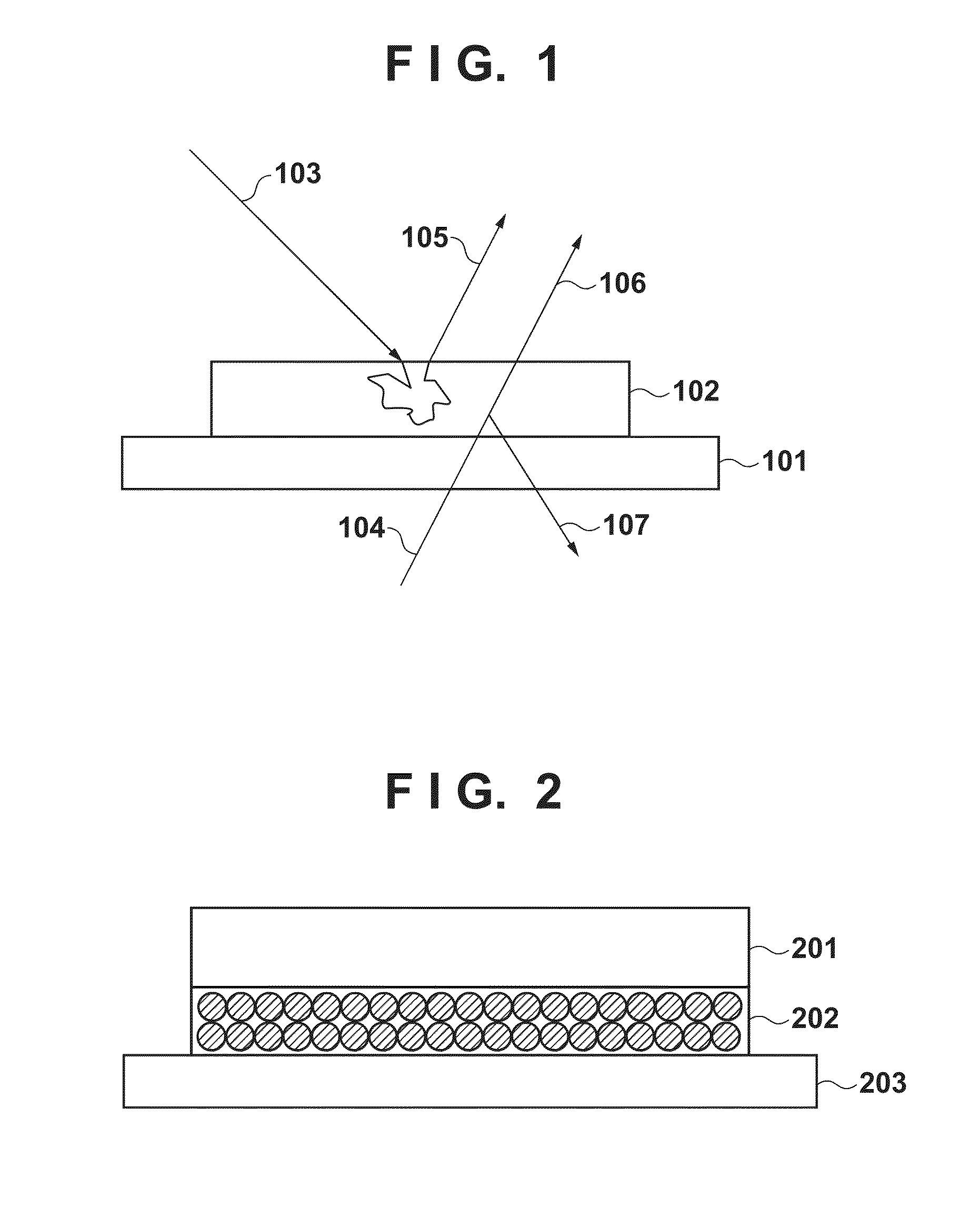
[0036]Prior to the description of image processing of this embodiment, color developing in consideration of transmitted light will be described below with reference to FIGS. 2 to 4 and FIG. 15.
[0037]FIG. 2 is sectional view of a printed product having an incomplete fixing layer in which toner is not completely fixed. In general, in an electrophotographic printer, toner transferred onto printing paper has a different degree of melting depending on degrees of heat and pressure in a fixing process. FIG. 2 shows toner layers 201 and 202 fixed on printing paper 203 under a certain fixing condition.
[0038]The toner layer 201 is a complete fixing layer in which toner particles are completely melted and fixed. The toner layer 202 is an incomplete fixing layer in which toner particles are not completely melted in a fixing process, and toner particles themselves and voids between toner particles are left. Since the toner l...
second embodiment
[0106]The second embodiment according to the present invention will be described below. The aforementioned first embodiment has explained the example in which the mounted amount of toner is controlled by the exposure control. However, the control method of the mounted amount is not limited to this example. The second embodiment will explain a method of controlling the mounted amount of toner using a developing condition. Note that since the arrangement of an image processing apparatus according to the second embodiment is the same as that of the first embodiment, the same reference numerals denote the same components, and a detailed description thereof will not be repeated. Only parts especially different from the first embodiment will be described below.
[0107]FIG. 13 is a block diagram showing the arrangement of the image processing apparatus of the second embodiment. A developing bias setting unit 1301 of the second embodiment sets a toner reduction ratio based on FIGS. 10A and 10...
embodiments
Modification of Embodiments
[0112]In the aforementioned first embodiment, the mounted amount of toner is controlled based on the toner reduction ratio by the exposure control. Also, in the second embodiment, the mounted amount of toner is controlled based on the toner reduction ratio by controlling the developing bias. However, the control method of the mounted amount of toner is not limited to these specific embodiments. For example, when the color separation unit 802 and gamma correction unit 804 selectively use tables corresponding to the toner reduction ratio, the mounted amount of toner may be controlled.
[0113]The aforementioned embodiments have explained the example in which the toner reduction ratio and fixing index are determined in accordance with information associated with transmittance of printing paper, a printing mode, and a use style of a printed product. However, the application range of the present invention is not limited to this example.
[0114]Since a printed produc...
PUM
 Abstract
Description
Claims
Application Information
 - R&D
- Intellectual Property
- Life Sciences
- Materials
- Tech Scout
- Unparalleled Data Quality
- Higher Quality Content
- 60% Fewer Hallucinations
Browse by: Latest US Patents, China's latest patents, Technical Efficacy Thesaurus, Application Domain, Technology Topic, Popular Technical Reports.
© 2025 PatSnap. All rights reserved.Legal|Privacy policy|Modern Slavery Act Transparency Statement|Sitemap|About US| Contact US: help@patsnap.com


