
Method and apparatus for identification of samples

a technology for identifying samples and samples, applied in the field of methods for identifying samples, can solve the problems of inherently less sensitive, inability to detect many types of bacteria, and slow technique, and achieve the effect of reducing collisions with neutral matrix molecules and minimising post-source decay

Active Publication Date: 2014-05-01
THERMO FISHER SCI BREMEN
View PDF13 Cites 23 Cited by
  • Summary
  • Abstract
  • Description
  • Claims
  • Application Information

AI Technical Summary

Benefits of technology

The present invention is a method for improving the resolution and sensitivity of mass spectrometry by using a multi-pass time-of-flight (TOF) mass spectrometer with a closed mirror arranged in a way that allows ions to travel multiple times along the path. This separation length is increased by overtaking other ions, leading to higher mass resolution. The method also uses a bi-directional ion deflector to generate data at both a high resolution and a wider mass range, resulting in more data points for deciding whether a sample microorganism matches microorganisms in a reference database. Overall, the invention provides for improved accuracy and sensitivity in mass spectrometry.

Problems solved by technology

This technique is slow (it takes at least some hours and may take days) and can miss many types of bacteria.
However, they are expensive and large and are inherently less sensitive than existing linear TOF mass spectrometers employed for biological identification.
The FTMS instruments such as the Orbitrap™ and FT-ICR MS instruments can provide very high sensitivity but have limitations on their mass range and are not suited to the larger singly charged species typically produced by a MALDI ion source.

Method used


Image

  • Method and apparatus for identification of samples
  • Method and apparatus for identification of samples
  • Method and apparatus for identification of samples

Examples


Embodiment Construction

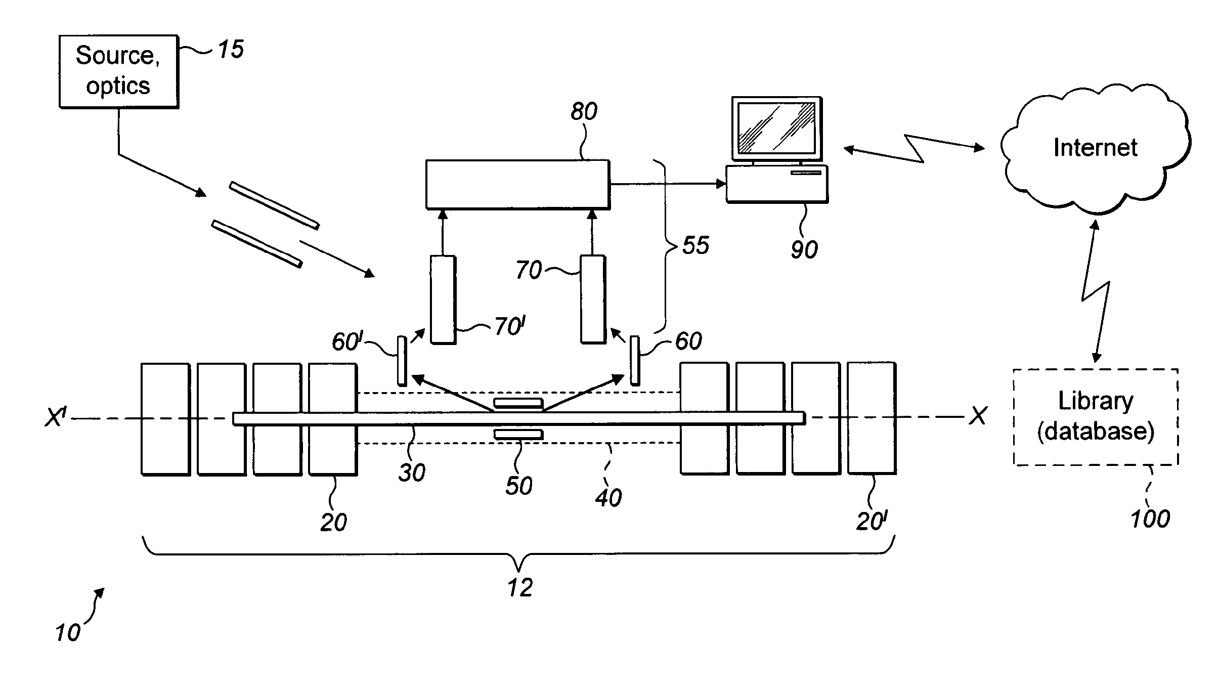
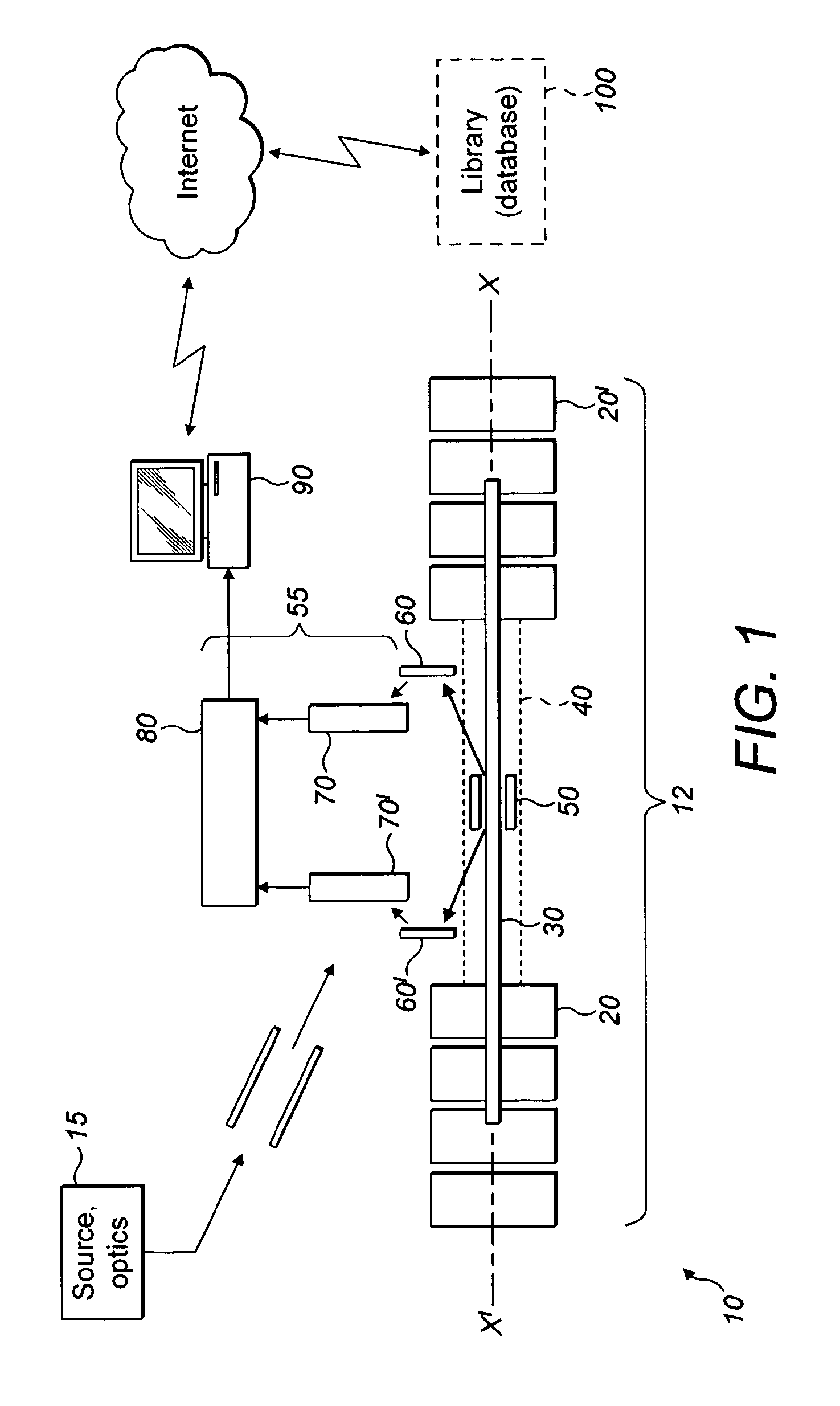
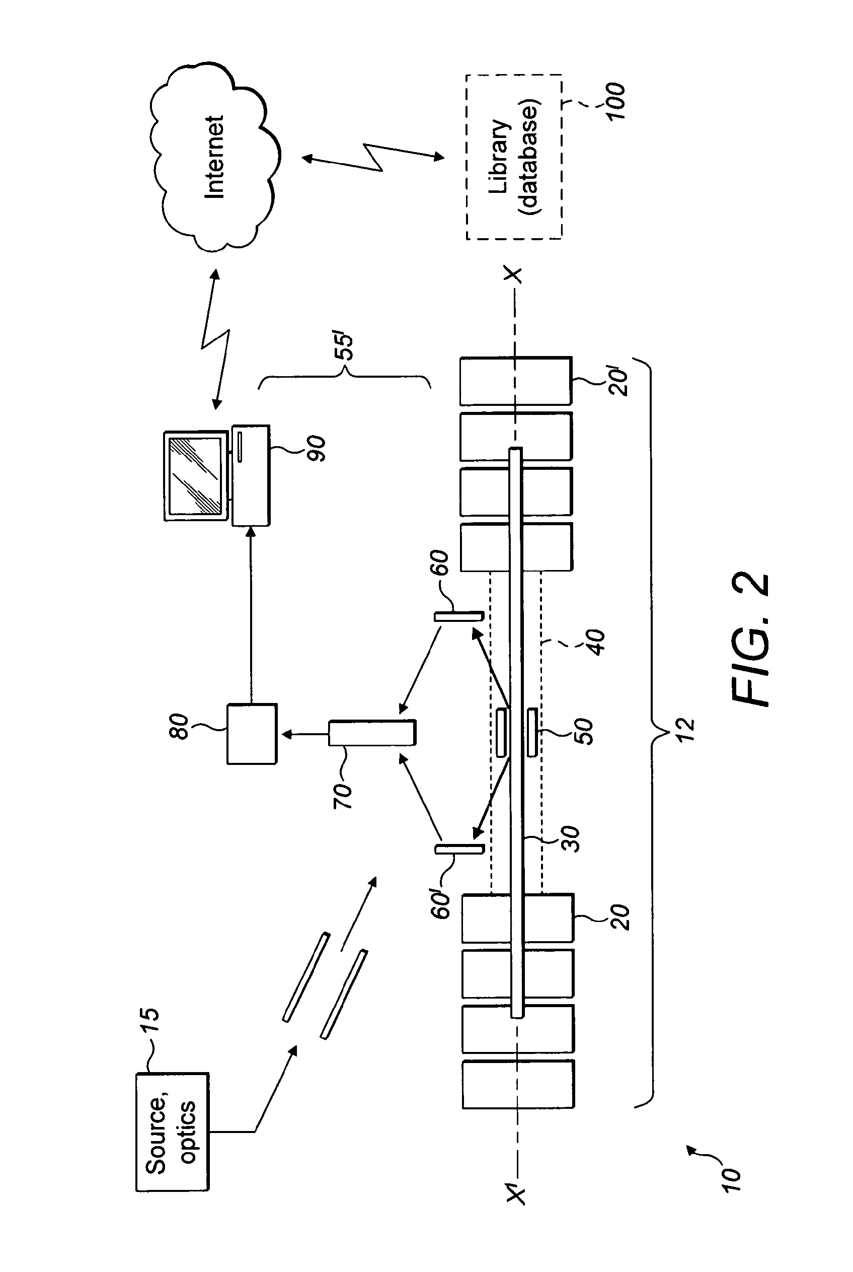
[0051]Referring first to FIG. 1, a multi-reflection time of flight (MR TOF) mass spectrometer instrument 10 is shown. The instrument 10 comprises a closed mirror MR TOF arrangement indicated generally by reference numeral 12 and an ion detection arrangement shown generally at reference numeral 55.

[0052]Ions are generated at an ion source and then guided using ion optics toward the closed mirror MR TOF 12. The ion source and optics is shown generally at reference numeral 15 in block form. The specific arrangement of the ion source and ion optics does not form a part of the present invention and in any event will be familiar to those skilled in the art. The ion source is, in preference, a matrix assisted laser desorption ionization (MALDI) source, although other ion sources such as an electrospray source may be used. As of 2011, bacterial electrospray ionization is not an established technique, however.

[0053]Ions generated by the ion source and guided by the ion optics 15 are directed...


PUM


Abstract

A multi reflection time of flight (MRTOF) mass spectrometer (12) And method for identifying a sample is disclosed. Sample ions are generated at an ion source (15). The MRTOF is a closed mirror arrangement with first and second opposed ion mirrors (20, 20′) on an axis of reflection (XX′). The MRTOF (12) also includes a bidirectional ion deflector (50) on that axis (XX′). The deflector (50) deflects ions onto the reflection axis as a short pulse at time to <zero> where they oscillate multiple times, separating in time of flight according to ion m / z. At a later time t, ions travelling in both directions along the axis (XX′) are ejected out of the MRTOF (12) by the bidirectional deflector (50) to an ion detector arrangement (55). The separation of ions in time of flight allows a “fingerprint” of a biological sample to be produced by the detector arrangement (55) without the need to assign a mass to each peak. Comparison with a library of fingerprints permits identification.

Description

FIELD OF THE INVENTION[0001]This invention relates to a method of identification of samples of unknown composition or type, particularly, but not exclusively, microbes such as bacterial or fungal colonies. It also relates to an apparatus for identification of samples such as microbiological organisms.BACKGROUND OF THE INVENTION[0002]Various different techniques for the analysis and identification of microbiological organisms such as bacterial or fungal colonies have been developed. For example, the technique of culture collection has been established for many years. Here, a sample of material to be identified / analysed is collected and this sample is then incubated to grow a culture which can then be analysed microscopically, for example. This technique is slow (it takes at least some hours and may take days) and can miss many types of bacteria.[0003]A second technique for microbiological analysis is so-called polymerase chain reaction (PCR). This procedure amplifies a specific regio...

Claims


Application Information

Patent Timeline
IPC IPC(8): H01J49/00H01J49/16H01J49/40
CPCH01J49/0031H01J49/406H01J49/164H01J49/408H01J49/0036H01J49/4245
Inventor GIANNAKOPULOS, ANASTASSIOS
Owner THERMO FISHER SCI BREMEN
Learn More