Method for controlling a technical apparatus

Active Publication Date: 2014-04-24
SIEMENS AG
View PDF5 Cites 0 Cited by
  • Summary
  • Abstract
  • Description
  • Claims
  • Application Information

AI Technical Summary

Benefits of technology

The patent describes a method that allows an apparatus to adjust its energy usage based on its actual energy demand. By monitoring the energy usage over time, the method can detect patterns in the demand and make adjustments that improve energy efficiency and save money. The method can also automatically shut down the apparatus when it is not needed, further reducing energy usage and costs. The patent also mentions that the method allows for automatic adjustment of the apparatus based on specific events, such as waking it up when there is an increase in energy demand or shutting it down when energy demand is lower.

Problems solved by technology

Furthermore, as a rule, the method also lengthens the service life of the technical apparatus by slowing down its rate of wear.

Method used


Image

  • Method for controlling a technical apparatus
  • Method for controlling a technical apparatus
  • Method for controlling a technical apparatus

Examples


Embodiment Construction

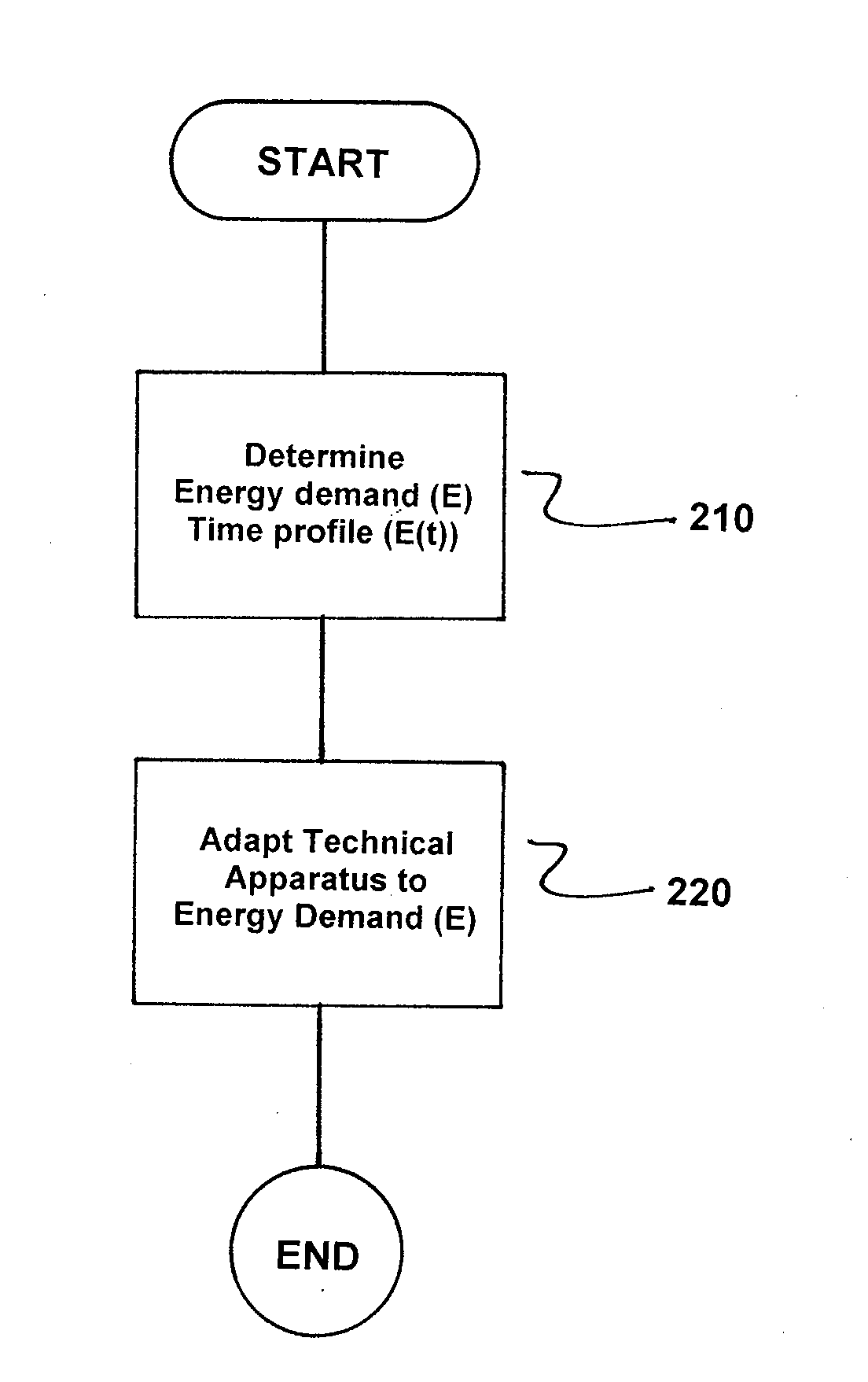
[0033]As for the technical apparatus, it can, by way of example, in this case be a pump, for example a coolant or hydraulic pump, or a compressor. The specific type and design of the technical apparatus is in fact, however, largely irrelevant in terms of the inventive method. However, the method enjoys particularly advantageous applications to slave apparatuses of larger technical systems because, in contrast to the larger systems, the slave apparatuses are frequently operated permanently in an unchanged operating state with a view to permanent availability, i.e., they are not shut down nor are they put into an energy-saving operation.

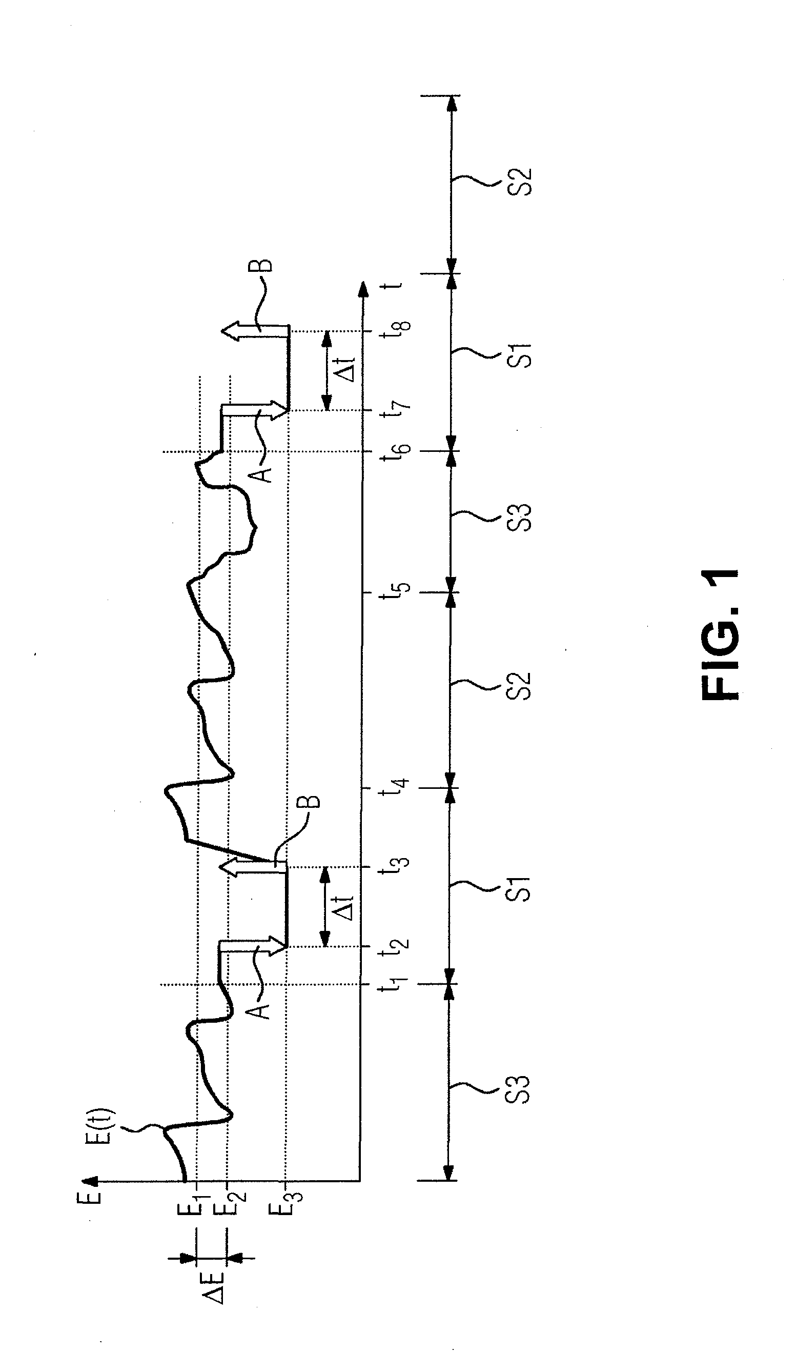
[0034]FIG. 1 shows a time profile E(t) of an energy demand E of the technical apparatus as a function of time t during three consecutive days.

[0035]There is also illustrated a corresponding shift pattern of work shifts S1, S2, S3 in a plant in which the technical apparatus is used. In this case, S1 denotes a night shift, S2 an early shift and S3 a late...


PUM


Abstract

The invention relates to a method for controlling a technical apparatus in which a time profile (E(t)) for a power requirement (E) for the technical apparatus is ascertained over at least one period and an operating state of the technical apparatus is matched to the ascertained power requirement (E) on the basis of time.

Description

[0001]REFERENCE TO RELATED APPLICATIONS[0002]This is a U.S. national stage of application No. PCT / EP2011 / 060333 filed 21 Jun. 2011.BACKGROUND OF THE INVENTION[0003]1. Field of the Invention[0004]The invention relates to a method for controlling a technical apparatus.[0005]2. Description of the Related Art[0006]Because of a potentially required demand, many technical apparatuses presently run permanently in a full-load operation, examples being air conditioning systems, hydraulic systems, air supply or extraction apparatuses.SUMMARY OF THE INVENTION[0007]It is an object of the invention to provide an improved method for controlling a technical apparatus.[0008]This and other objects are achieved in accordance with the invention by providing a method for controlling a technical apparatus, in which a time profile of an energy demand of the technical apparatus is determined from at least one period, and an operating state of the technical apparatus is adapted to the determined energy dem...

Claims


Application Information

Patent Timeline
IPC IPC(8): G06Q50/06
CPCG06Q50/06G05B19/0426G05B2219/25289
Inventor HASSEL, JORGKONOPKA, FRANK
Owner SIEMENS AG
Why Eureka
Try Eureka