
Log management system and log management method

a management system and log management technology, applied in the field of log management system and log management method, can solve the problems of difficult server system, unrealistic operation, and inability to perform debugging using the same method as normal software, and achieve the effect of easy tracking, efficient inclusion, and without deteriorating the productivity of server module developmen

Inactive Publication Date: 2014-04-17
HITACHI SOFTWARE ENG
View PDF7 Cites 59 Cited by
  • Summary
  • Abstract
  • Description
  • Claims
  • Application Information

AI Technical Summary

Benefits of technology

The present invention provides a log management system that can efficiently analyze logs without affecting the development of a server module. By using the history of failures and bugs, developers can easily identify and fix issues in the server system, improving its overall operation rate. The system also allows for easy tracking of logs and efficient debugging, resulting in improved productivity during server module development.

Problems solved by technology

On the other hand, it is difficult in the server system with the cluster configuration to perform an operation (hereinafter, referred to as “debug”) of identifying the cause of a trouble of software being run at the time of occurrence of the trouble.
However, the server system with the cluster configuration is a special system because plural cluster nodes perform a process in cooperation with each other, and thus the debug cannot be performed using the same method as normal software.
This operation is unrealistic, and thus the debug for the server system is generally performed by analyzing log data that is a record obtained by executing software.
However, it is not generally easy to analyze the log data in the server system with the cluster configuration because the pieces of log data are dispersed and stored into plural cluster nodes due to the configuration of plural cluster nodes in the server system.
This makes the debug operation difficult, thus becoming a factor for a long failure recovery time.
In addition, it is difficult to analyze the output format of log data in a general system.
Accordingly, if the output format of log data in which the association with the user request can be identified is not employed, it is difficult to analyze the log data, thus becoming a factor for a long failure recovery time.
However, it is not considered to simplify a detailed analysis for each request or each communication session.
However, it is not easy.
Therefore, it is possible that a load on a software developer is increased, the productivity of development of the server module is deteriorated, and the configuration of software of the server module is complicated.

Method used


Image

  • Log management system and log management method
  • Log management system and log management method
  • Log management system and log management method

Examples


Embodiment Construction

[0033]Hereinafter, an embodiment according to the present invention will be described using FIG. 1 to FIG. 8.

[0034]First, a configuration of a log management system according to an embodiment of the present invention will be described using FIG. 1 and FIG. 2.

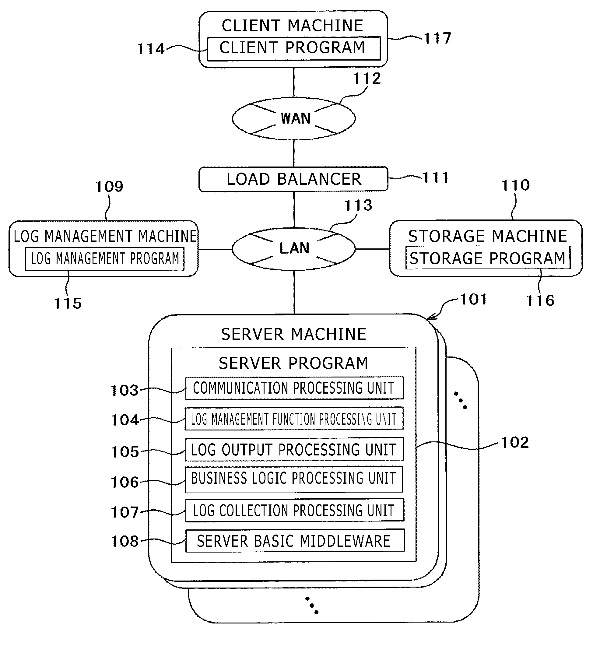
[0035]In the log management system of the embodiment, as shown in FIG. 1, a plurality of server machines 101, a log management machine 109, a load balancer 111, and a storage machine 110 are connected to each other via a local area network (LAN) 113, and the load balancer 111 and a client machine 117 are connected to each other via a wide area network (WAN) 112.

[0036]The server machine 101 is a computer device that executes a server program 102. The server machine 101 may be a general personal computer (PC), or a dedicated machine specialized in server functions such as a blade server. Only one server machine 101 may be provided, or a cluster configuration in which plural server machines 101 are combined with each other may be p...


PUM


Abstract

A server system generates one thread with respect to a request for a process, and at the time, a thread local storage that is a dedicated area in which data used for the thread is stored is secured on a main storage device. Log tracking information that can uniquely identify output of a log from the start of output of the log to the end of output of the same is held in the thread local storage during a process of a session ID, a user ID, and a sequence number. When the log is output, the log tracking information is added to the log data to be output to an auxiliary storage device.

Description

CLAIM OF PRIORITY[0001]The present application claims priority from Japanese patent application serial no. 2012-229721, filed on Oct. 17, 2012, the content of which is hereby incorporated by reference into this application.BACKGROUND OF THE INVENTION[0002]1. Field of the Invention[0003]The present invention relates to a log management system and a log management method, and particularly to a log management system and a log management method in which logs can be centrally managed without placing a load of software development on a system developer in a cluster system.[0004]2. Description of the Related Art[0005]In general, a server system is configured using plural machines. This configuration is referred to as “cluster configuration”, and each machine configuring the cluster is referred to as “cluster node”. By employing the cluster configuration, the server system can disperse a processing load, and can provide a standby function in which when a cluster node is down during a proces...

Claims


Application Information

Patent Timeline
Patent Type & Authority Applications(United States)
IPC IPC(8): G06Q10/06
CPCG06Q10/06316G06Q10/0639
Inventor FUKUI, DAISUKESASAKI, SHINYA
Owner HITACHI SOFTWARE ENG
Learn More