
Ion generating apparatus and air purifying apparatus

a technology of generating apparatus and air purification apparatus, which is applied in the direction of lighting and heating apparatus, heating types, instruments, etc., can solve the problems of not being able to recognize whether or not ions are actually generated, contaminants tend to remain in the room, and the ventilation by opening a window may not be as desired, so as to increase the amount of ions discharged into the room, the effect of reducing the amount of ions in the air

Inactive Publication Date: 2015-04-14
SHARP KK
View PDF39 Cites 1 Cited by
  • Summary
  • Abstract
  • Description
  • Claims
  • Application Information

AI Technical Summary

Benefits of technology

[0066]According to the present invention, the ions generated by the ion generating section can be included in the air at the laminar flow section where the flowing air becomes laminar flow, allowing the air to efficiently include the ions generated by the ion generating section and increasing the amount of ions included in the air. Hence, the amount of ions discharged into a room can be increased.
[0067]According to the present invention, a plurality of ion generators are periodically driven in different phases. This prevents each ion generator from being affected by the ions generated by another ion generator while the rate of energization decreases, extending the operational lifetime as an ion generating apparatus. Hence, the operation lifetime can be extended without much decrease in the amount of ions dispersed in the space where ions are discharged.
[0068]According to the present invention, when the ion generating apparatus is placed in the air-flowing path such that the juxtaposed direction of the ion generating sections is approximately perpendicular to the direction of airflow passing through near the ion generating sections, the ions generated by the ion generating sections are prevented from overlapping and interfering with each other.
[0069]This can prevent mutual interference of ions and can alleviate decrease in ion generation efficiency, even when the ion generators are arranged in a collective manner.

Problems solved by technology

Moreover, such contaminants tend to remain in a room due to recent improvement in house airtightness, requiring active air ventilation.
In a room located in an area with serious air pollution or in a room where a person having an allergy to pollens lives or works, however, an air purifying apparatus is used, since ventilation by opening a window may not be possible as desired.
It is not easy to recognize whether or not ions are actually generated, since the generated ions are colorless and odorless.
One ion generator may, however, generate only a limited amount of ions.
In such a case, placement of ion generators in an air-flowing path, which is suitable for ion generation, causes a number of space constraints including safety requirements.

Method used


Image

  • Ion generating apparatus and air purifying apparatus
  • Ion generating apparatus and air purifying apparatus
  • Ion generating apparatus and air purifying apparatus

Examples


embodiment 1

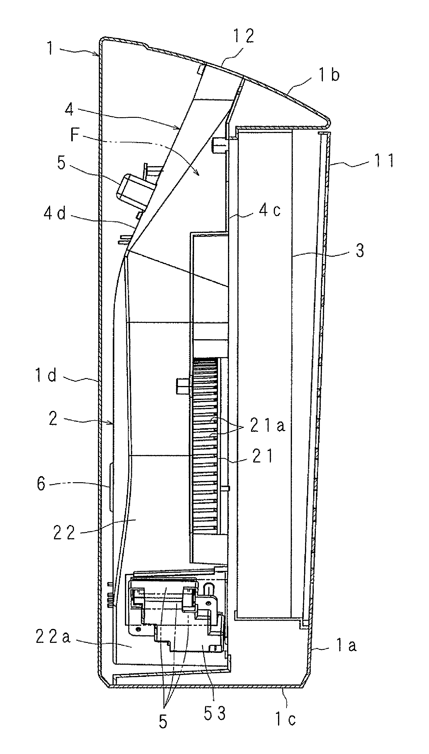
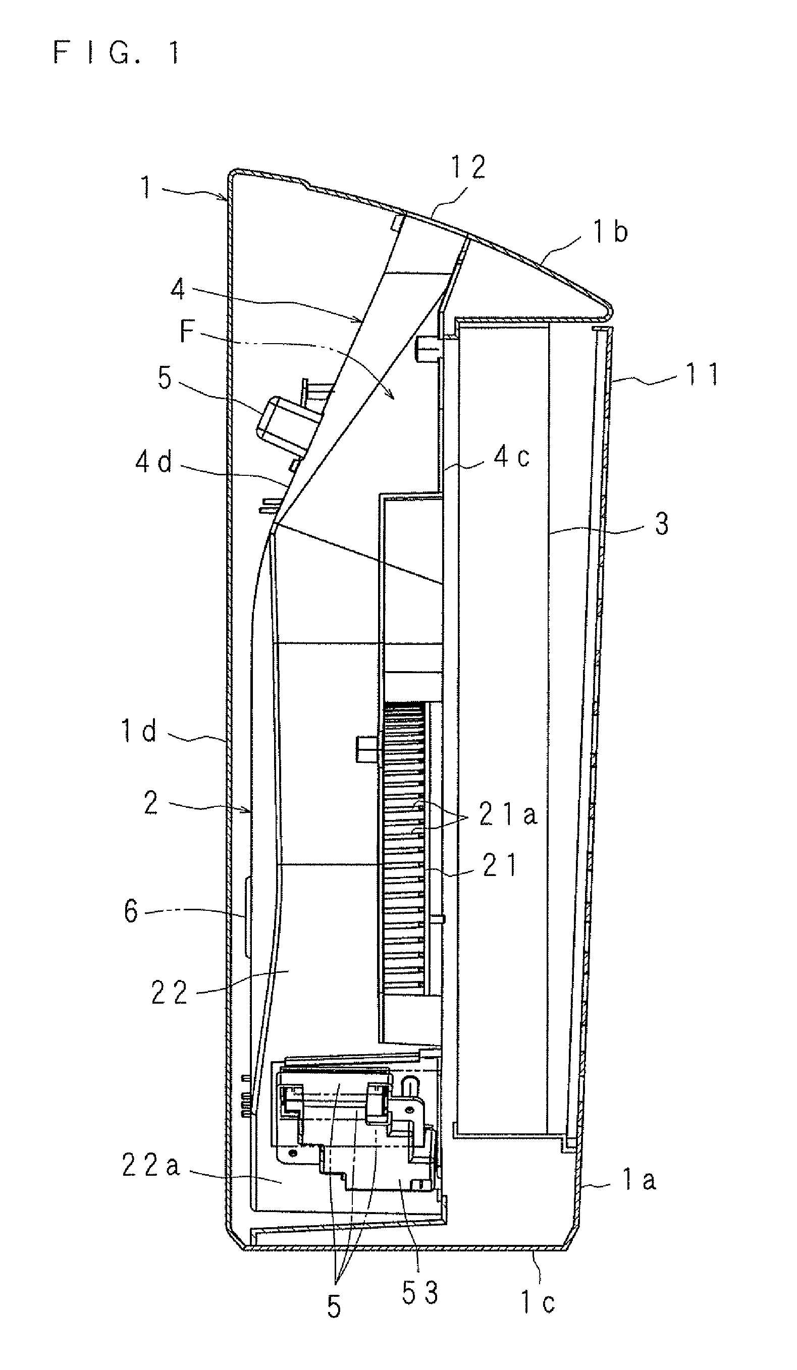
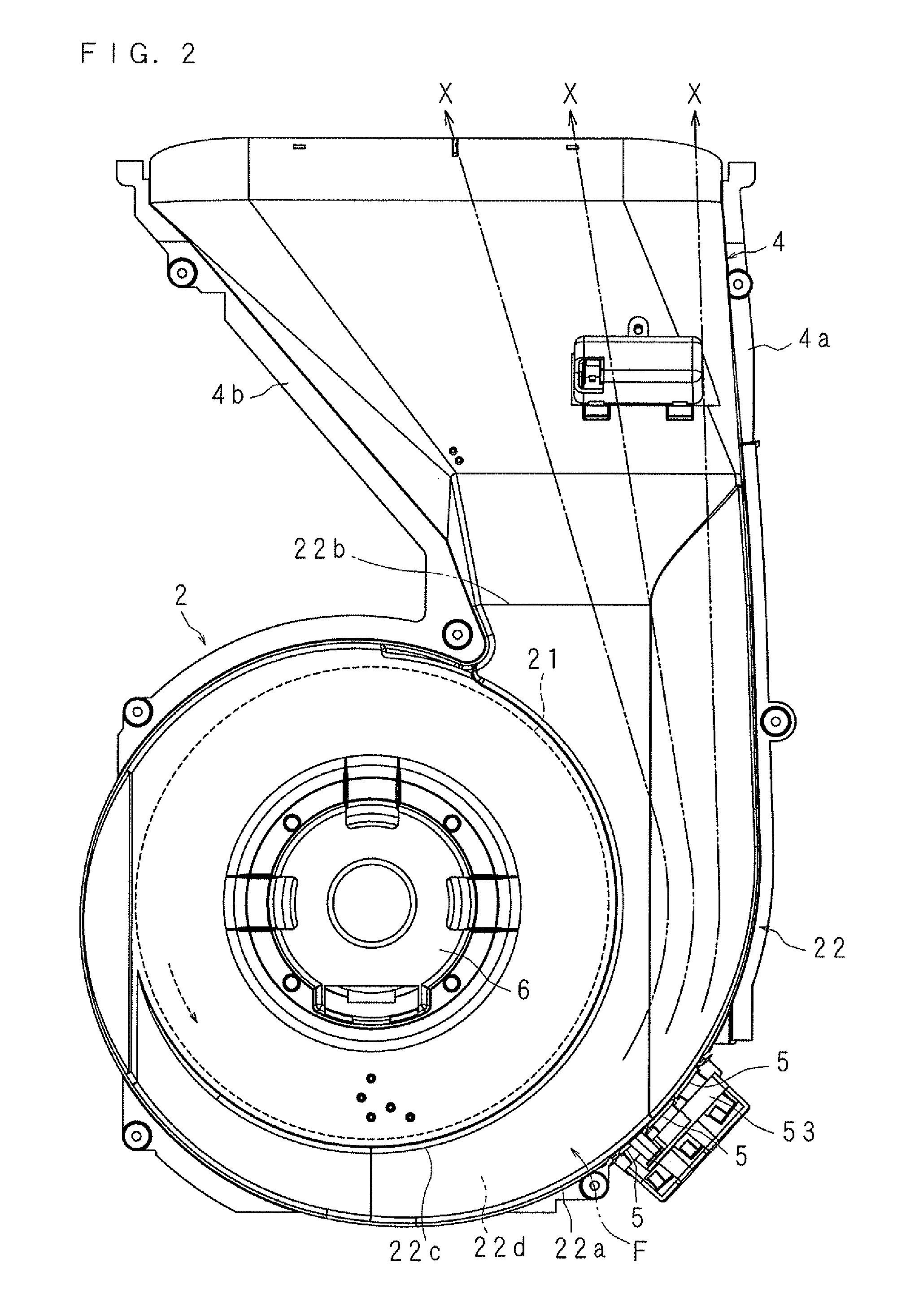
[0135]The present invention will be described in detail based on the drawings illustrating an embodiment thereof. Here, an air purifying apparatus is described as an example. FIG. 1 is a vertical section side view illustrating the configuration of an air purifying apparatus according to the present invention. FIG. 2 is a front view illustrating the configuration of a main part, FIG. 3 is a side view illustrating the configuration of a main part, and FIG. 4 illustrates a front view of the configuration of an ion generator and FIG. 4B illustrates a side view of the configuration of an ion generator.

[0136]The air purifying apparatus illustrated in FIG. 1 includes: a housing 1 having a suction port 11 on a back wall 1a and having a discharge port 12 on a top wall 1b; an air-blower 2 arranged at a lower part in the housing 1; a filter 3 arranged inside of the suction port 11 to let through the air suctioned from the suction port 11 by the air blower 2 while eliminating foreign materials ...

embodiment 2

[0162]An embodiment in which the ion generating apparatus according to the present invention is applied to an air purifying apparatus will be described below. FIG. 6 is a vertical section side view illustrating the configuration of an air purifying apparatus according to the present invention. FIG. 7 is a front view illustrating the configuration of a main part.FIG. 8 is a side view illustrating the configuration of a main part.

[0163]The air purifying apparatus illustrated in FIG. 6 includes: a housing 1 having a suction port 11 on a back wall 1a and a discharge port 12 on a top wall 1b; an air blower 2 arranged at a lower part in the housing 1; a filter (purifier) 3 arranged inside of the suction port 11 and letting through the air suctioned by the air blower 2 from the suction port 11 to eliminate foreign materials in the air and to produce clean air; a duct 4 arranged as an air-guiding path between the air blower 2 and the discharge port 12 to guide the clean air toward the disch...

embodiment 3

[0211]Embodiments in which an ion generating apparatus according to the present invention is applied to an air purifying apparatus will be described below. FIG. 17 is a vertical section side view illustrating the configuration of an air purifying apparatus according to the present invention. FIG. 18 is a front view illustrating the configuration of a main part. FIG. 19 is a side view illustrating the configuration of a main part. FIG. 20 is a front view illustrating an outer appearance of an ion generating apparatus.

[0212]Reference numeral 1 in the drawings denotes a housing having a shape of an approximately rectangular parallelepiped. The housing 1 includes a suction port 11 on a back wall 1a for taking in the room air. Ahead the suction port 11, a filter (purifier) 3 is arranged for removing foreign materials from the air suctioned from the suction port 11 by the air blower 2 arranged at a lower part in the housing 1 and producing clean air. Above the air blower 2, a duct 4 is ar...


PUM

PropertyMeasurementUnit
timeaaaaaaaaaa
voltageaaaaaaaaaa
ion concentrationaaaaaaaaaa

Abstract

A housing having a suction port and a discharge port, an impeller 21 and a casing 22 that houses the impeller 21, an air blower 2 housed in the housing, a filter that lets through the air suctioned from the suction port by the air blower 2, and two ion generating sections that generate positive and negative ions are provided. The ion generating section is arranged on a circular-arc guide wall 2a in the casing 22. The positive and negative ions generated by the ion generating section are efficiently included in the air passing through as laminar flow along the circular-arc guide wall 22a.

Description

1. FIELD OF THE INVENTION[0001]The present invention relates to an ion generating apparatus and an air purifying apparatus that discharge ions generated by an ion generating section into a room together with the air suctioned by an air blower to purify the air in the room.2. DESCRIPTION OF THE RELATED ART[0002]Air in a residential room is contaminated with dust of mites, allergic substances such as pollens, floating fungus, virus, foul odors and the like. Moreover, such contaminants tend to remain in a room due to recent improvement in house airtightness, requiring active air ventilation. In a room located in an area with serious air pollution or in a room where a person having an allergy to pollens lives or works, however, an air purifying apparatus is used, since ventilation by opening a window may not be possible as desired.[0003]The air purifying apparatus includes: an air blower housed in a housing having a suction port on a back surface thereof and a discharge port at an upper...

Claims


Application Information

Patent Timeline
Patent Type & Authority Patents(United States)
IPC IPC(8): A61L9/22B03C3/38F24F3/16
CPCA61L9/22B03C3/383A61L2209/134F24F2003/1635F24F2003/1682Y02A50/20F24F8/194F24F8/30H01T23/00F24F3/16F24F13/28
Inventor TSUDA, TSUTOMUYOSHIMURA, ICHIRONISHIDA, HIROMU
Owner SHARP KK
Learn More