Testing a Hardware Emulation Model of a Circuit with Software Checker Routines Designed for an RTL Model of the Circuit

a hardware emulation model and circuit technology, applied in the field of circuit design verification, can solve the problems of insufficient speed to allow large circuit designs to be tested, inability to introduce errors into the design, and comparatively more difficult to achieve the test of the hardware emulation model of the circuit to ensure that it is functioning correctly

Inactive Publication Date: 2014-04-10
APPLE INC
View PDF10 Cites 9 Cited by
  • Summary
  • Abstract
  • Description
  • Claims
  • Application Information

AI Technical Summary

Benefits of technology

The patent describes a system and method for testing the operation of a circuit design using hardware emulation and software checker routines. The hardware emulation system may show that the circuit is functionally correct, and the software checker routines can then analyze the circuit's behavior to ensure it is operating correctly. This approach allows for faster and more efficient testing of circuit designs, as it doesn't require the software checker routines to run simultaneously with the hardware emulation system. The method also allows for easier debugging of circuit designs, as the state information from the hardware emulation system can be stored and used by the software checker routines at a later time.

Problems solved by technology

Due to the large number of these electronic components and the complexity of their interconnections, the design process for most circuits does not begin at the transistor level, but instead starts at a higher level of abstraction.
At each level of the circuit design process, it is possible for errors to be introduced into the design.
If these errors remain undetected then they can end up in the physical circuit when it is manufactured.
RTL simulation can be relatively easy, accurate, flexible, and low cost, but it is often not fast enough to allow large circuit designs to be tested, and the RTL level is still highly abstracted from the end goal of producing a transistor-level specification that can be used to build a physical implementation of the circuit.
However, testing the hardware emulation model of the circuit to ensure that it is functioning correctly can be comparatively more difficult to achieve than testing the RTL model used in the software-based RTL simulation.

Method used


Image

  • Testing a Hardware Emulation Model of a Circuit with Software Checker Routines Designed for an RTL Model of the Circuit
  • Testing a Hardware Emulation Model of a Circuit with Software Checker Routines Designed for an RTL Model of the Circuit
  • Testing a Hardware Emulation Model of a Circuit with Software Checker Routines Designed for an RTL Model of the Circuit

Examples


Embodiment Construction

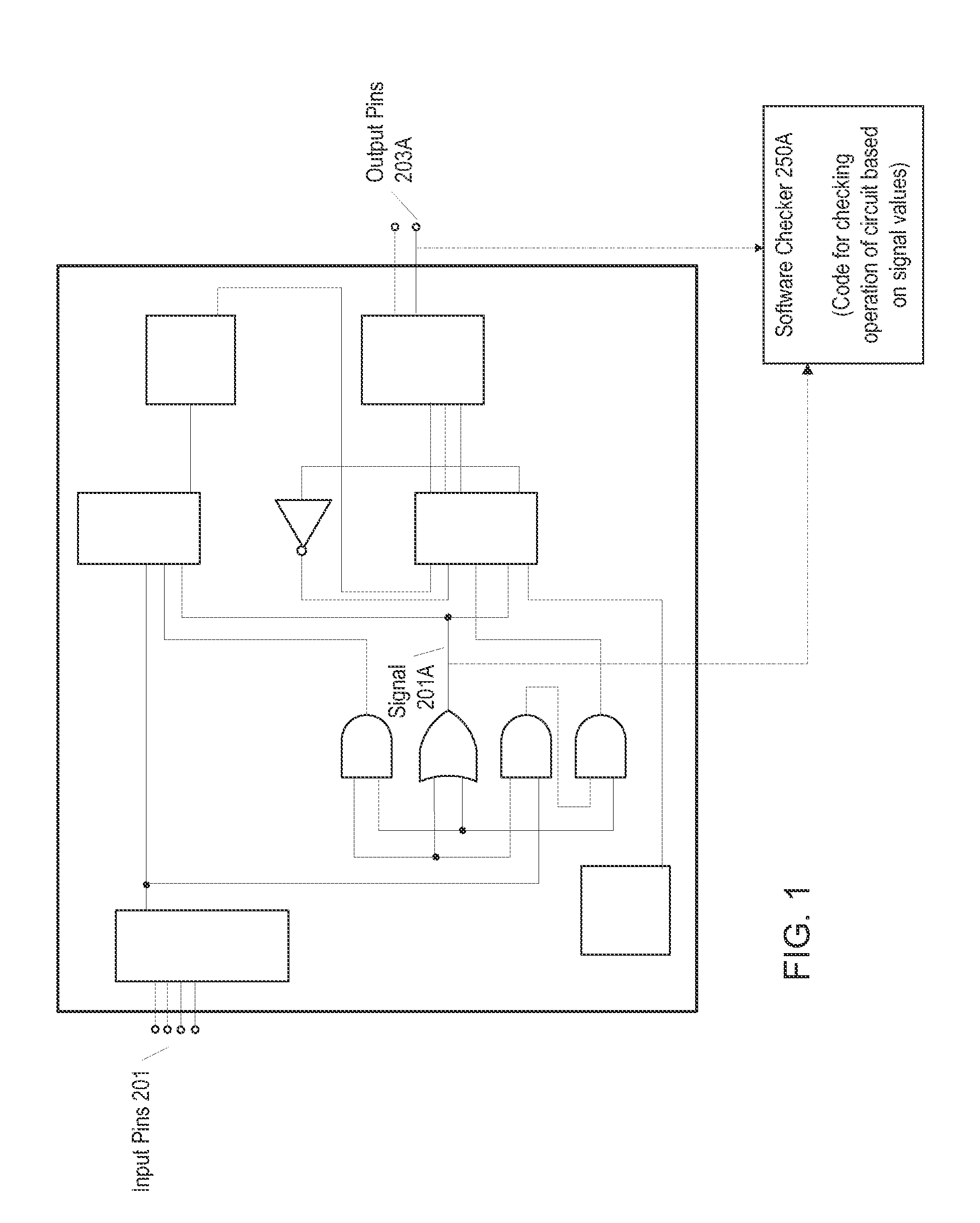
[0022]Various embodiments of a system and method for performing circuit design verification are described. The circuit under design may be any kind of electronic circuit. For example, in some embodiments the circuit under design may be an integrated circuit (IC) or system-on-a-chip (SoC). In other embodiments the circuit may be a component or sub-circuit used in a chip or other larger circuit. The circuit may be intended for use in any type of system, device, or product. For example, in some embodiments the circuit may be used in a mobile phone or other handheld electronic device (e.g., after the design process has finished and after the physical circuit has been manufactured).

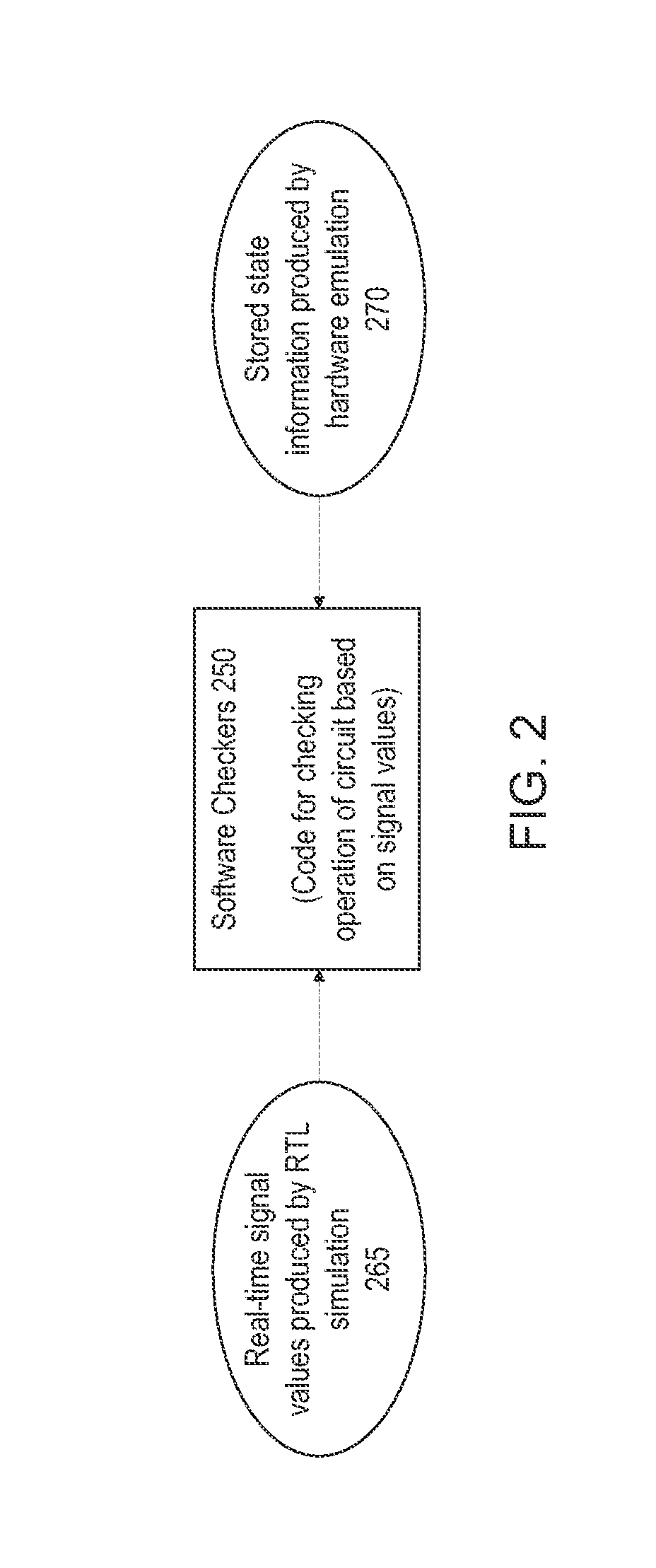
[0023]The circuit design process may include emulating the circuit on a hardware emulation system and verifying or testing the circuit operation for functional correctness. More particularly, the hardware emulation may be tested by executing one or more software checker routines on a test bench computer system...


PUM


Abstract

A hardware emulation system may emulate a plurality of cycles of a circuit, and may store state information at each cycle which specifies signal values for one or more signals of the circuit. After the hardware emulation has finished, the state information may be streamed from the memory of the hardware emulation system to a different storage device that is accessible by a computer system that executes one or more software checker routines. The computer system may execute the software checker routines, which may include passing the signal values specified in the state information to the software checker routines on a cycle-by-cycle basis similarly as if the software checker routines were receiving them in real time directly from the hardware emulation system.

Description

BACKGROUND[0001]1. Field of the Invention[0002]This application is related to the field of circuit design verification, e.g., testing an electronic circuit design to determine whether it is operating correctly.[0003]2. Description of the Related Art[0004]Electronic circuits are composed of individual electronic components, such as transistors, resistors, capacitors, inductors and diodes, connected by conductive wires or traces through which electric current can flow. Due to the large number of these electronic components and the complexity of their interconnections, the design process for most circuits does not begin at the transistor level, but instead starts at a higher level of abstraction. For example, the circuit design process may begin by specifying an abstract diagram of the circuit architecture which illustrates the functional components of the circuit and how they operate together to perform the required functionality of the circuit. From this initial design, the circuit d...

Claims


Application Information

Patent Timeline
Patent Type & Authority Applications(United States)
IPC IPC(8): G06F17/50
CPCG06F30/331
Inventor BURES, EDMOND R.LENT, JEFFREY V.BOEHM, FRITZ A.
Owner APPLE INC
Why Eureka
Try Eureka