
Filtering distributor plate for supplying a fixed bed reactor having a co-current downflow of gas and liquid for the treatment of heavy clogging feeds

a distributor plate and fixed bed technology, which is applied in the direction of liquid-gas reaction process, hydrocarbon oil cracking, chemistry apparatus and processes, etc., can solve the problems of high risk of chimney damage, long fitting time, and uneven distribution of liquid flow ra

Active Publication Date: 2014-04-10
INST FR DU PETROLE
View PDF1 Cites 36 Cited by
  • Summary
  • Abstract
  • Description
  • Claims
  • Application Information

AI Technical Summary

Benefits of technology

The present invention is a distributor plate for a gas-liquid flow in a fixed bed reactor. The plate has a filtration function and is designed to transform the bi-phase jet of the gas-liquid mixture into a gas-liquid mixture that is uniformly distributed over the catalyst bed. The plate has a unique design with a perforated support, a filtration layer, and a full plate with distribution elements. The plate also has high porosity dispersive elements located below the full plate to disperse the liquid jet. The invention provides a fixed bed reactor with a co-current downflow gas-liquid flow with a distribution and filtration plate suitable for the trickle mode of operation. The plate is positioned upstream of each catalyst bed and is constituted by a perforated support, a filtration layer, and a full plate with distribution elements. The invention also includes a distribution and filtration plate for a gas-liquid flow in a fixed bed reactor with a co-current downflow gas-liquid flow.

Problems solved by technology

This patent proposes a configuration for the filtration plate in which the chimneys have perforated holes (or slots) in the middle of the catalytic bed, which may cause difficulties in the case of a blockage of the bed in the proximity of the holes.
This blockage of the bed would, as a consequence, cause the blockage of the chimney, with two outcomes: an imbalance in the distribution of the liquid flow rate below the distributor plate, and a risk of damage to the chimneys when dismantling the plate if the chimneys are aggregated with and stuck to the catalytic bed;patent FR 2 959 677 describes an arrangement of removable baskets containing filtration particles and catalyst particles, said baskets being deposited on the distributor plate in order to facilitate fitting / dismantling of said plate and to limit the risk of aggregation between the plate and the catalyst.
However, that solution suffers from a certain number of disadvantages: a large number of baskets, meaning that the fitting time is very long, and the need to ensure fluid contact between all of the baskets, while preventing particles from escaping between the baskets.

Method used


Image

  • Filtering distributor plate for supplying a fixed bed reactor having a co-current downflow of gas and liquid for the treatment of heavy clogging feeds
  • Filtering distributor plate for supplying a fixed bed reactor having a co-current downflow of gas and liquid for the treatment of heavy clogging feeds

Examples


Embodiment Construction

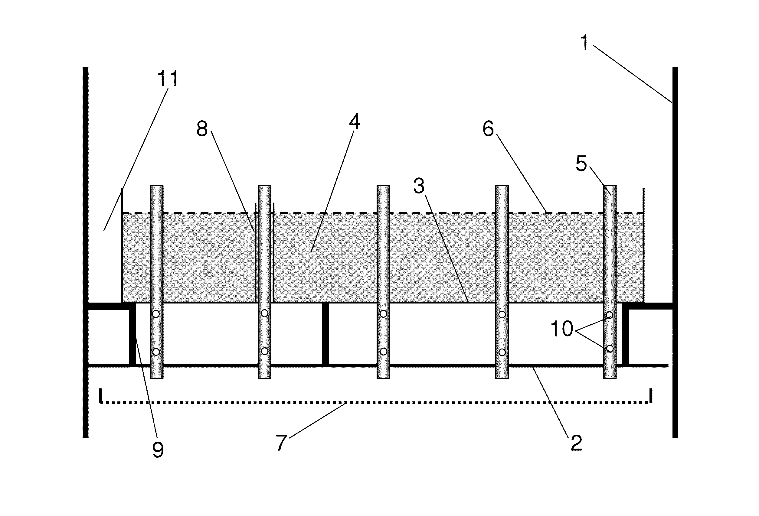
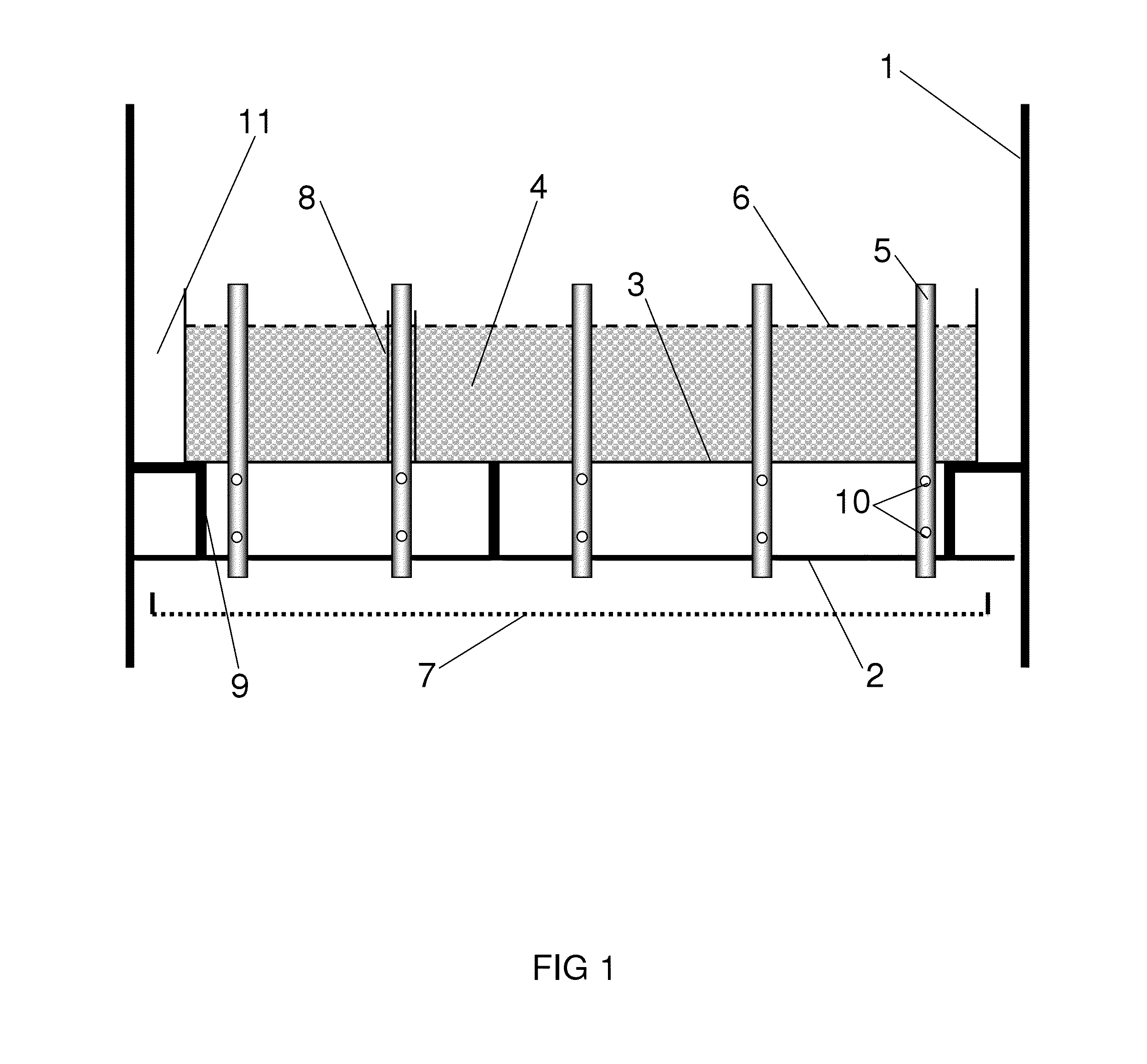
[0037]The distributor plate of the present invention is a distributor plate in the sense that it transforms the two-phase jet (gas-liquid) entering the reactor into a gas-liquid mixture which is homogeneous and uniformly distributed over the surface of the catalytic bed located downstream. In addition, it integrates a filtration function, but differs from prior art filtration plates in that the filtration function is disconnected from the distribution function.

[0038]The perforated support (3) on which the filtration layer (4) is deposited is located in a central zone of the plate but does not occupy the whole of the section of the reactor. In fact, there is an annular space (11) between the filtration zone (4) and the walls of the reactor (1).

[0039]This annular space (11) allows liquid to pass towards the distribution elements (5) in the situation in which the filtration layer (4) is blocked by the various impurities recovered over time.

[0040]The width of this annular space is set s...


PUM


Abstract

The present invention describes a distributor plate adapted to co-current downflow flows of gas and of liquid, more particularly in the “trickle” mode, said distributor plate integrating a filtration function separate from the distribution function.

Description

FIELD OF THE INVENTION[0001]The present invention relates to the context of plates for filtering and distributing gas and liquid at the inlet to fixed bed type catalytic reactors operating in trickle flow mode (co-current downflow, liquid speed below 1.5 cm / s). The principal application envisaged is the hydrotreatment of residues, although the present application may be applied to any hydrogenation of oil cuts that could cause clogging of the fixed bed, and even more generally to any liquid phase, with or without gas, charged with clogging particles arriving at a fixed bed.EXAMINATION OF THE PRIOR ART[0002]The present invention can be viewed as an improvement to several patents filed by the Applicant:[0003]patent FR 2 924 950 describes a filtration plate known as a pre-distribution plate, with an overflow tube for a fixed bed reactor with a co-current downflow of gas and of liquid, that pre-distribution plate consisting of a filtration plate placed above a conventional distributor p...

Claims


Application Information

Patent Timeline
IPC IPC(8): B01J8/02
CPCB01J8/0242B01J8/025B01J8/0278B01J8/0453B01J8/0492B01J2208/025C10G49/002B01J8/24B01J8/44B01J19/24
Inventor BAZER-BACHI, FREDERICHAROUN, YACINEDIGNE, MATHIEU
Owner INST FR DU PETROLE
Learn More