
Brake chamber, boot member, and bush member

a technology of bush member and brake chamber, which is applied in the direction of braking system, machine/engine, engine diaphragm, etc., can solve the problems of reducing the strength of the connection portion, reducing the efficiency of the braking system, and reducing the cost of the system. , to achieve the effect of simplifying and costing the structur

Active Publication Date: 2014-04-10
TECH UNIV DARMSTADT +1
View PDF5 Cites 7 Cited by
  • Summary
  • Abstract
  • Description
  • Claims
  • Application Information

AI Technical Summary

Benefits of technology

The patent text discusses the issue of connecting a housing and a cylinder to form an accommodation space for a diaphragm. If the two parts are separate, foreign matter like mud can enter the connection portion, which can cause strength reduction. The text proposes a solution without adding extra costs by using a sealing surface and a sealing ring to prevent moisture from entering the chamber. This results in a simplified and cost-reduced structure. The technical effect is achieved by using one sealing means to deal with moisture entering the chamber from both sides, thereby simplifying the overall structure and reducing expenses.

Problems solved by technology

In this case, foreign matter such as mud may enter the inside of the housing through the opening and the foreign matter may further invade the inside of the cylinder, causing a risk of inhibiting the operation of the push plate.
If the housing and the cylinder are connected by welding, for example, moisture in foreign matter may rust the welded part, causing a risk of strength reduction at the connection portion.
Meanwhile, additionally providing means dedicated to preventing entry of foreign matter with the intention of solving this problem in turn leads to cost increase of the system.

Method used


Image

  • Brake chamber, boot member, and bush member
  • Brake chamber, boot member, and bush member
  • Brake chamber, boot member, and bush member

Examples


Embodiment Construction

[0068]An embodiment of the present invention will now be described by referring to the drawings. The embodiment is described below on condition that it is merely an embodiment of the present invention and is not intended to limit the invention.

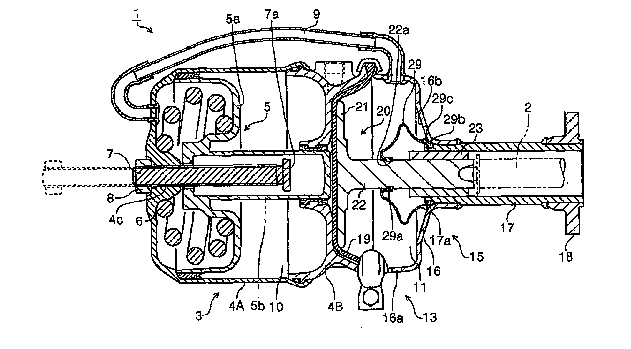
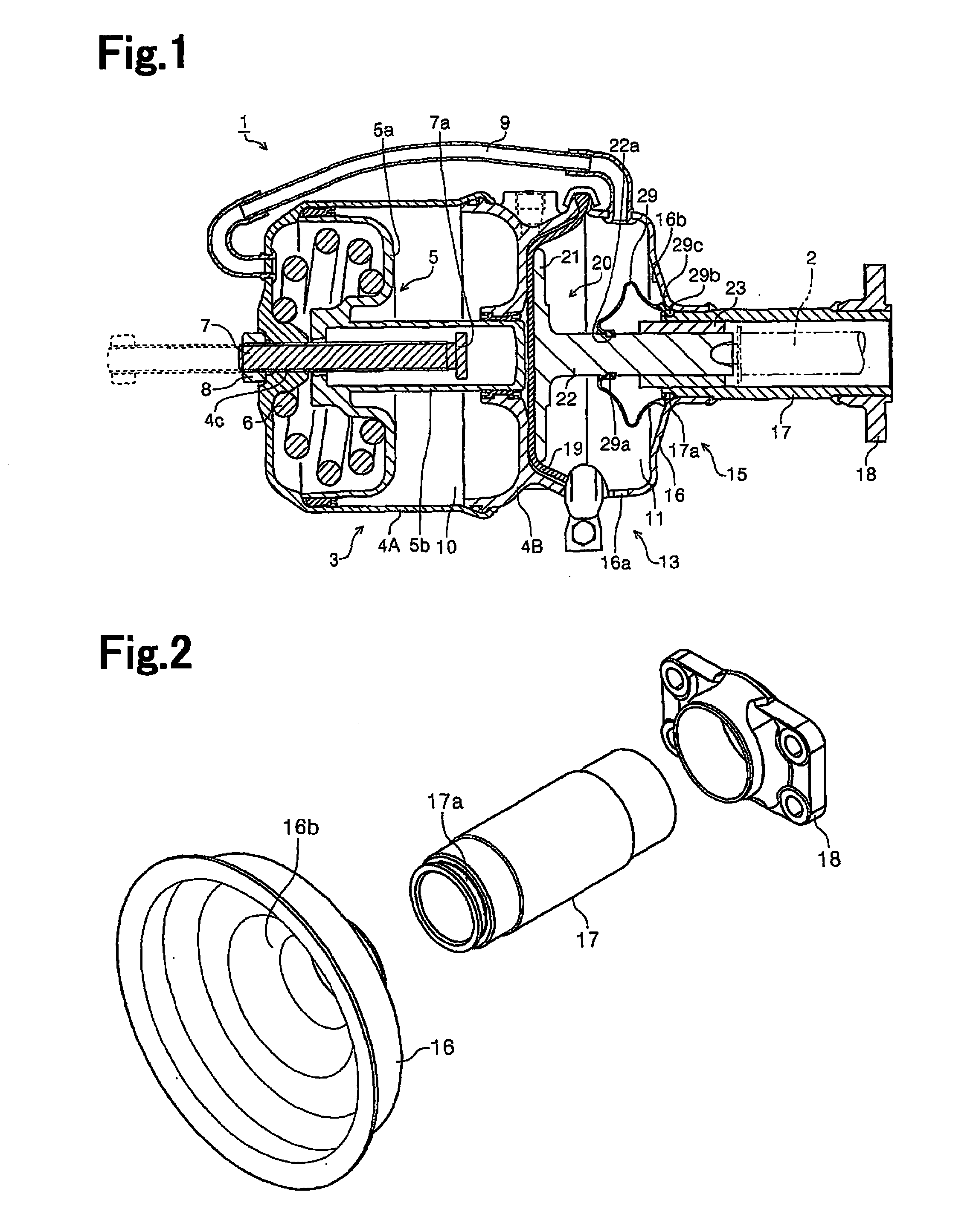
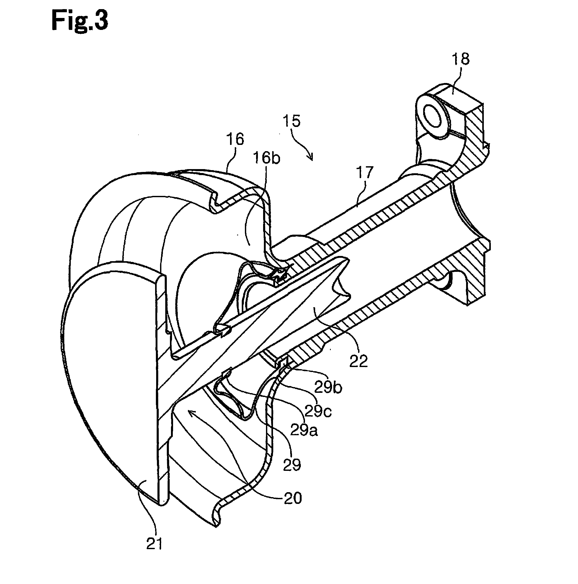
[0069]FIG. 1 is a cross-sectional side view of a brake chamber 1 of the present invention. FIG. 2 is an exploded perspective view of a base 15. FIG. 3 is a perspective view showing the cross sections of the base 15, a push plate 20, and a dust boot 29. FIG. 4 is a cross-sectional side view of a part where the dust boot 29, a cup 16, and a cylinder 17 are connected. FIG. 5 is a cross-sectional side view of a part where the dust boot 29, the cup 16, and the cylinder 17 are connected in a different embodiment.

[0070]In FIG. 1, a brake device (not shown) is provided on the right side of the brake chamber 1. A pushrod indicated by a sign 2 proceeds into the brake device to push a brake shoe of the brake device outward, thereby generating braking for...


PUM


Abstract

A brake chamber includes a rod member that makes reciprocating motion within a cylinder through a pressure of compressed air or an urging force of a spring, thereby causing a pushrod for activating a brake device of a vehicle to proceed into the brake device. The brake chamber further includes a diaphragm that deforms in response to supply of the compressed air to push the rod member, and a housing that forms an accommodation space for the diaphragm. The housing is connected to the cylinder with a first end of the cylinder being inserted in the housing. The brake chamber further includes a boot member connected to the cylinder and the rod member. The boot member includes a sealing portion to prevent entry of foreign matter into a connection portion between the housing and the cylinder by contacting an inner circumferential surface of the housing.

Description

RELATED APPLICATIONS[0001]The present is a National Phase entry of PCT Application No. PCT / JP2012 / 060801, filed Apr. 16, 2012, which claims priority from Japanese Patent Application No. 2011-090039, filed Apr. 14, 2011, Japanese Patent Application No. 2011-090047, filed Apr. 14, 2011, and Japanese Patent Application No. 2011-112525, filed May 19, 2011, the disclosures of which are hereby incorporated by reference herein in their entirety.FIELD OF THE INVENTION[0002]The present invention relates to a brake chamber including a rod member that makes reciprocating motion within a cylinder through the pressure of compressed air or the urging force of a spring, thereby causing a pushrod for activating a brake device of a vehicle to proceed into the brake device. The present invention also relates to a boot member in the brake chamber that functions to prevent entry of foreign matter into the cylinder.[0003]The present invention further relates to a bushing member in the brake chamber that...

Claims


Application Information

Patent Timeline
IPC IPC(8): B60T11/00
CPCB60T11/00B60T13/38F16J3/04F16J15/52B60T17/083F16J3/02
Inventor SHIMOMURA, TAKEONISHIMURA, AKINORI
Owner TECH UNIV DARMSTADT
Learn More