Liquid Ejecting Apparatus, and Non-Transitory, Computer-Readable Media Therefor

a liquid ejecting apparatus and non-transitory technology, applied in the direction of printing, other printing apparatus, etc., can solve the problems of increasing the size of the liquid ejecting apparatus, affecting the recording performance of the peripheral circuit, etc., to reduce the degradation, or prevent the degradation of recording performance

Active Publication Date: 2014-04-03
BROTHER KOGYO KK
View PDF3 Cites 6 Cited by
  • Summary
  • Abstract
  • Description
  • Claims
  • Application Information

AI Technical Summary

Benefits of technology

[0010]A liquid ejecting apparatus having a configuration disclosed herein enables the liquid ejecting apparatus to reduce or prevent degradation of recording p

Problems solved by technology

However, the increase in number of signal lines may result in various drawbacks, such as greate

Method used


Image

  • Liquid Ejecting Apparatus, and Non-Transitory, Computer-Readable Media Therefor
  • Liquid Ejecting Apparatus, and Non-Transitory, Computer-Readable Media Therefor
  • Liquid Ejecting Apparatus, and Non-Transitory, Computer-Readable Media Therefor

Examples


Embodiment Construction

[0020]Hereafter, example embodiments of the present application will be described with reference to the drawings.

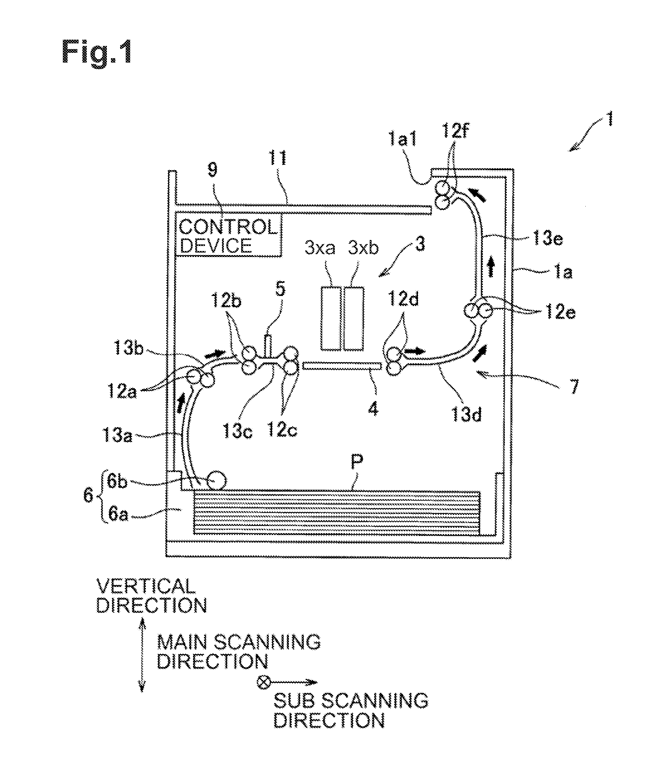
[0021]Referring first to FIG. 1, a general configuration of an ink jet printer 1 will be described.

[0022]The printer 1 may include a casing 1a of a rectangular block shape. A paper discharge tray 11 may be provided on a top plate of the casing 1a. Inside the casing 1a, an ink jet head 3 (hereinafter, simply head 3), a platen 4, a paper sensor 5, a paper feed unit 6, a conveying device 7, a control device 9 and so forth are enclosed. A convey route along which a paper sheet P is conveyed from the paper feed unit 6 to the paper discharge tray 11 is configured inside the casing 1a, as indicated by arrows in FIG. 1.

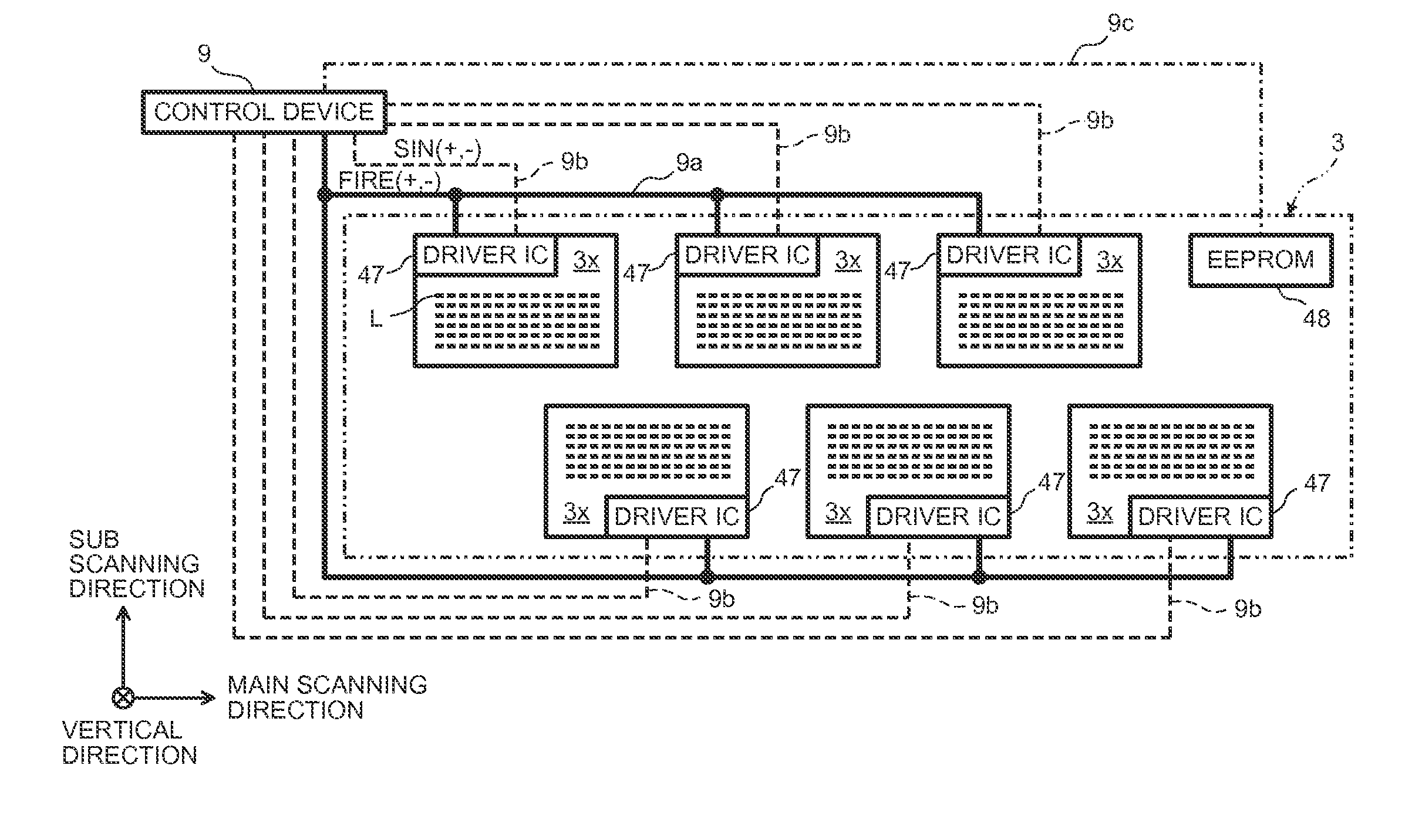
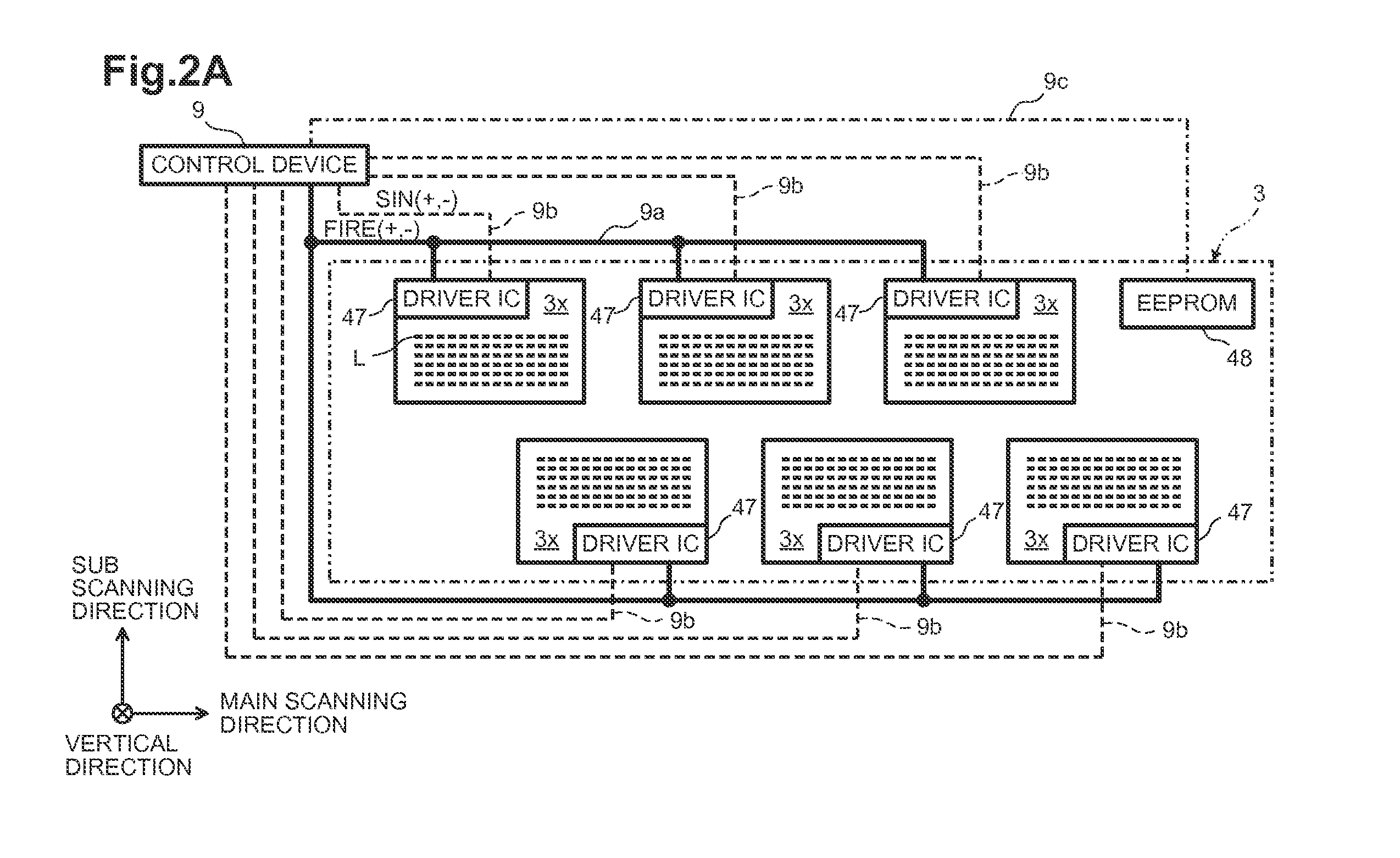
[0023]The head 3 may include three head units 3xa and three head units 3xb arranged in a checkerboard pattern with an interval therebetween, in a main scanning direction (see FIGS. 2A, 2B). Although the head units 3xa and the head units 3xb may have the same struct...


PUM


Abstract

A liquid ejecting apparatus may have a head with a plurality of head units. Each head unit may include a driver IC. An ejection timing signal (FIRE) may be transmitted from a control device to each of the driver ICs through an ejection timing signal line, which may be connected to the control device as a single line and split on its way to the driver ICs. The control device may further output delay information indicating a delay amount for the FIRE signal to the driver ICs through a control signal line through which a waveform pattern selection signal (SIN) is also transmitted. Each of the driver ICs may include a delay circuit that delays the FIRE signal by the delay amount indicated by the delay information.

Description

CROSS REFERENCE TO RELATED APPLICATION[0001]This application claims priority from Japanese Patent Application No. 2012-218359, filed on Sep. 28, 2012, the disclosure of which is incorporated herein by reference in its entirety.BACKGROUND[0002]1. Technical Field[0003]The present disclosure relates to a liquid ejecting apparatus including a liquid ejecting head that ejects a liquid through a nozzle, and a non-transitory computer-readable medium for the liquid ejecting apparatus.[0004]2. Description of the Related Art[0005]Liquid ejecting apparatuses thus far developed include a serial printing type that makes a liquid ejecting head reciprocate in a main scanning direction for recording, and a line printing type in which the liquid ejecting head is fixed. The liquid ejecting head of the line printing type liquid ejecting apparatus typically includes a plurality of head chips aligned therein.BRIEF SUMMARY[0006]In the foregoing line printing type apparatus, when the location of the plura...

Claims


Application Information

Patent Timeline
IPC IPC(8): B41J2/045
CPCB41J2/04573B41J2/04541B41J2/04553B41J2/0458B41J2/04581B41J2/04591B41J2/04595B41J2/04596
Inventor SUZUKI, KATSUAKI
Owner BROTHER KOGYO KK
Why Eureka
Try Eureka