Vehicular display device

Active Publication Date: 2014-04-03
YAZAKI CORP
View PDF4 Cites 14 Cited by
  • Summary
  • Abstract
  • Description
  • Claims
  • Application Information

AI Technical Summary

Benefits of technology

The vehicular display device described in this patent allows for the virtual image to automatically change positions based on external light levels, ensuring visibility in both conditions. The device can also automatically return to the original position if the light levels change. Additionally, the device can be positioned at the front of the vehicle to reduce the influence of external light. The device can easily inform the driver of the virtual image position. Overall, the device provides sufficient visibility and reduces the need for driver viewpoint movement and focusing, making it useful as a head-up display for vehicles.

Problems solved by technology

However, for example, in a situation where a strong external light from the sun is arrived, such as daytime of a clear day, a light intensity of the external light becomes larger than that of the virtual image displayed by the head-up display device, and as a result, display of the virtual image is difficult to be visually recognized due to the influence of the external light.
Nevertheless, because the head-up display device performs display by the projected virtual image, when the intensity of the external light is very large, such as daytime of a clear day, the influence of the external light is too strong even if the light intensity of the virtual image is increased.
As a result, it is impossible to ensure a sufficient visibility.
However, if the virtual image is projected to such a location, the driver has to increase movement of the viewpoint or needs focusing of the eyes to see the virtual image, and thus a function as the head-up display device cannot be sufficiently exhibited.

Method used


Image

  • Vehicular display device
  • Vehicular display device
  • Vehicular display device

Examples


Embodiment Construction

[0027]Specific illustrative embodiments relating to a vehicular display device of the present invention will be now described with reference to the accompanying drawings.

[0028]

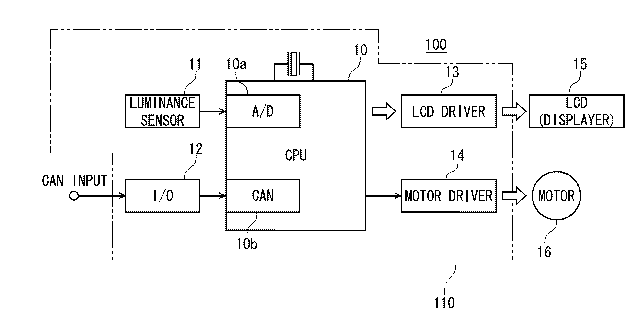
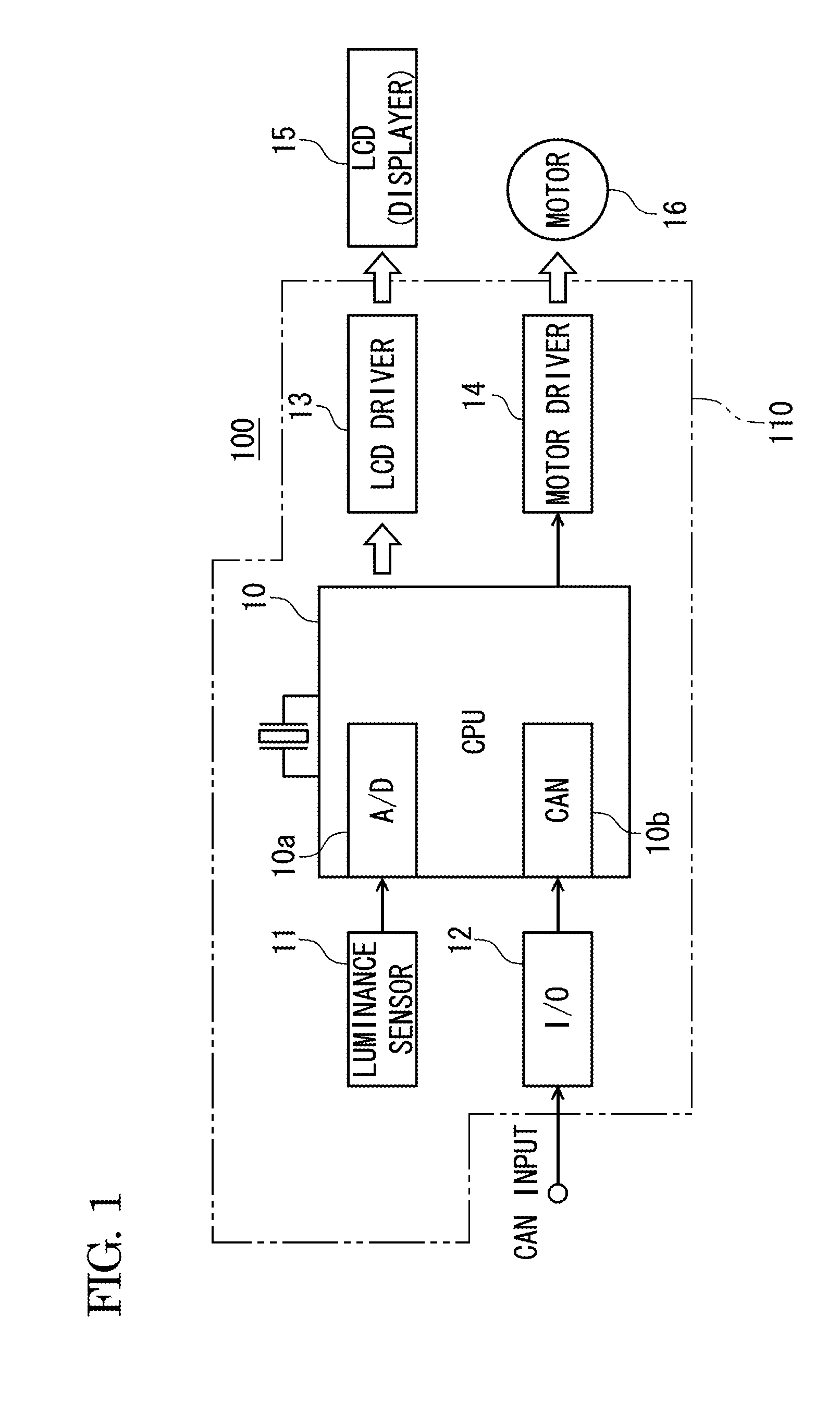
[0029]A configuration example of an electric circuit of a HUD (head-up display) device main body 100 according to the present embodiment is shown in FIG. 1. As shown in FIG. 1, the electric circuit of the HUD device main body 100 includes a control circuit 110, a liquid crystal displayer (LCD) 15 and an electric motor 16, and the liquid crystal displayer 15 and the electric motor 16 are connected to the control circuit 110.

[0030]The control circuit 110 includes a microcomputer (CPU) 10, an illuminance sensor 11, an input / output interface (I / O) 12, a LCD driver 13, and a motor driver 14.

[0031]The microcomputer 10 implements various functions required by the HUD device main body 100, by executing a pre-installed program. Also, the microcomputer 10 has an A / D conversion processing unit 10a and a CAN communication...


PUM


Abstract

A vehicular display device includes a display unit that displays visible information, a light projection unit that includes a reflection member which reflects light containing the visible information displayed on the display unit and projects the reflected light to a predetermined observation region to display the visible information as a virtual image, a light path adjustment mechanism that switches an imaging position of the virtual image between at least two positions, an illuminance detection unit that detects an intensity of external light affecting visibility of the virtual image, and an imaging position control unit that controls the light path adjustment mechanism depending upon the illuminance and changes the imaging position to a first position, at which the virtual image is less influenced by the external light, or to a second position, at which the virtual image is easily influenced by the external light.

Description

CROSS REFERENCE TO RELATED APPLICATION[0001]This application is based on Japanese Patent Applications No. 2012-217574 filed on Sep. 28, 2012, the contents of which are incorporated herein by reference.BACKGROUND OF THE INVENTION[0002]1. Technical Field[0003]The present invention relates to a vehicular display device having a display unit for displaying visible information and a light projection unit for reflecting light containing the visible information displayed on the display unit by a predetermined light reflection member to project the light to a predetermined observation region, and displaying the visible information as a virtual image.[0004]2. Background Art[0005]In a vehicular display device, a head-up display (HUD) having good visibility may be used to allow a driver to rapidly recognize information having, for example, a small information amount but a high degree of urgency.[0006]The vehicular head-up display guides a light image, which contains visible information general...

Claims


Application Information

Patent Timeline
IPC IPC(8): G02B27/01
CPCG02B27/0179G02B27/0149G02B2027/0118G02B2027/0159
Inventor MASUDA, AKIRAIWAMOTO, TAKESHI
Owner YAZAKI CORP
Why Eureka
Try Eureka