
Wireless power supply apparatus, filter unit and power supply apparatus for robot using the filter unit

Active Publication Date: 2014-04-03
DENSO WAVE INC +1
View PDF5 Cites 36 Cited by
  • Summary
  • Abstract
  • Description
  • Claims
  • Application Information

AI Technical Summary

Benefits of technology

The patent text is about a wireless power supply apparatus that can efficiently transmit electric power without increasing the size of machines. It also includes a filter unit that can easily change its filter characteristics. Additionally, the text describes a power supply apparatus for a robot that can transfer control signals without emitting electromagnetic waves, even in situations where electric power and signals are superimposed and transferred wirelessly.

Problems solved by technology

There is a problem that, in order to obtain sufficient electric power the load connected to the resonant coil, the size of the power transmission coil and the resonant coil has to be increased.
In addition, since both of the resonant coil and the exciting coil for power conversion are essential, there is another problem of increasing the size of the configuration as a whole.
The large size of the wireless power supply apparatuses is a serious impediment in introducing the apparatuses to facilities and robots.
However, wireless transfer or superimposition of electric power and signals may raise a problem of causing communication errors and emission of noise.
Such communication errors and emission of noise may lead to stoppage of the machines and lowering of operating rate due to the stoppage.
Thus, the size of the power reception coil will not be increased.
However, when the power reception coil and the actual load are directly connected as mentioned above, the function of the power reception coil as a repeater may be impaired, depending on the activation conditions of the actual load.

Method used


Image

  • Wireless power supply apparatus, filter unit and power supply apparatus for robot using the filter unit
  • Wireless power supply apparatus, filter unit and power supply apparatus for robot using the filter unit
  • Wireless power supply apparatus, filter unit and power supply apparatus for robot using the filter unit

Examples


first embodiment

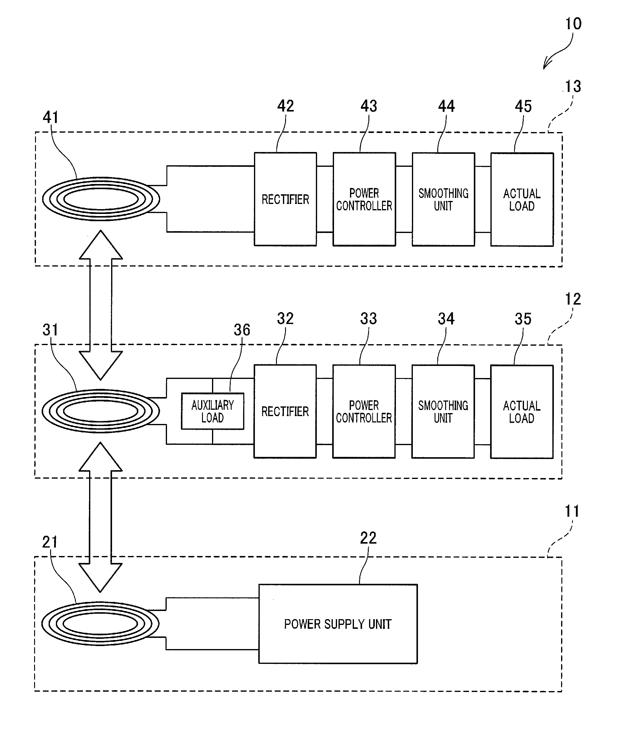
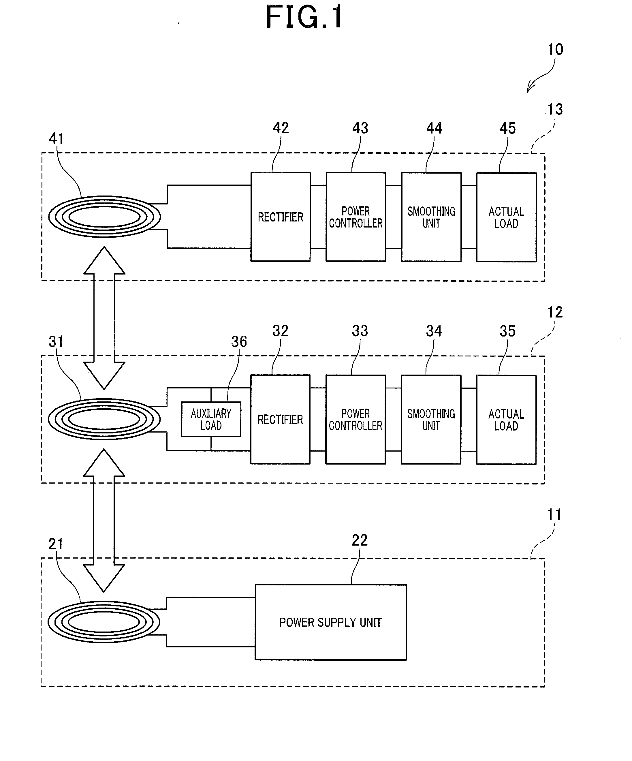
[0053]As shown in FIG. 1, a wireless power supply apparatus 10 according to a first embodiment includes a power transmission module 11, an intermediate module 12 and an end module 13. In the first embodiment, the wireless power supply apparatus 10 is set up in a facility, such as a factory, to wirelessly supply electric power from the power transmission module 11 to the intermediate module 12 and the end module 13. In applying the wireless power supply apparatus 10 to a facility, such as a factory, electric power is wirelessly supplied from the power transmission module 11 to the intermediate module 12 and the end module 13.

[0054]The power transmission module 11 includes a power transmission coil 21 and a power supply unit 22. As shown in FIG. 2, the power supply unit 22 is configured by an electric circuit that includes a power source 23 of alternating current, switching elements 24 and 25 and a gate driver 26. The switching elements 24 and 25 are configured such as by field effect...

second embodiment

[0120]In a second embodiment, as shown in FIG. 9, the intermediate module 12 of the wireless power supply apparatus 10 includes an actual load acquisition unit (corresponding to actual load acquiring means) 336 and a load change unit (corresponding to load changing means) 337. Specifically, the CPU 331 of the intermediate module 12 executes a computer program to realize the actual load acquisition unit 336 and the load change unit 337 in software. The actual load acquisition unit 336 and the load change unit 337 may be realized in hardware as an electric circuit integrated into the CPU 331, or may be realized in the combination of hardware and software.

[0121]In the second embodiment, the intermediate module 12 includes an auxiliary load 50 that is a variable load whose magnitude is changeable. For example, the auxiliary load 50 is configured such as by a variable coil or a variable capacitor. The actual load acquisition unit 336 acquires, from the actual load 35 of the intermediate ...

third embodiment

[0130]In a third embodiment, as shown in FIG. 10, the wireless power supply apparatus 10 of the embodiments described above is applied to an industrial articulated robot (hereinafter just referred to as “robot”) 60.

[0131]The robot 60 has a plurality of arms which are rotatable about the respective axes. In FIG. 10, as a simplified example, the robot 60 includes a first arm 61, a second arm 62 and a seat base 63. The first arm 61 is provided to the seat base 63, which is fixed to the facility, so as to be relatively turned about the center axis, relative to the seat base 63. The first and second arms 61 and 62 are mutually turned about a joint 64 as a fulcrum. The second arm 62 has a functional part 65 at an end portion that is opposite to the first arm 61. The functional part 65 realizes various functions such as of a manipulator or a camera.

[0132]In the robot 60, the power transmission module 11 is provided to the seat base 63. The electric power outputted from the power transmissi...


PUM


Abstract

A wireless power supply apparatus includes a power reception coil, an actual load and an auxiliary load. The power reception coil functions as a repeater for receiving electric power in a non-contact manner by magnetic resonance with a power transmission coil to which electric power is supplied from a power supply unit and relaying transfer of the electric power from the power transmission coil. The actual load is connected to the power reception coil and is powered by the electric power received by the power reception coil. The auxiliary load is inserted parallel to the power reception coil and the actual load and forms a closed circuit with the power reception coil when supply of the electric power to the actual load is interrupted to be in an open state.

Description

CROSS-REFERENCE TO RELATED APPLICATION[0001]This application is based on and claims the benefit of priorities from earlier Japanese Patent Application Nos. 2012-216194 filed Sep. 28, 2012 and 2013-064018 filed Mar. 26, 2013, the descriptions of which are incorporated herein in their entirety by reference.BACKGROUND[0002]1. Technical Field[0003]The present invention relates to a wireless power supply apparatus, a filter unit and a power supply apparatus for a robot using the filter unit.[0004]2. Related Art[0005]Recently, a wireless power supply using magnetic resonance is proposed. The wireless power supply realizes an electric power supply by generating magnetic resonance between a power transmission coil and a power reception coil (see U.S. Pat. No. 7,825,543). As is well known, such wireless power supply using magnetic resonance includes a repeater coil acting as a relay of power transfer. The repeater coil has a resonant frequency equivalent to that of the power reception coil a...

Claims


Application Information

Patent Timeline
IPC IPC(8): H01F38/14
CPCH01F38/14H02J50/50H02J50/12H02J50/70H02J50/90
Inventor SUGINO, MASAYOSHIYUASA, KATSUMIHAMASAKI, KEISUKEKONDOH, HIROSHITAKEDA, SHIGERUHASEO, YASUYUKI
Owner DENSO WAVE INC
Learn More