
Energy recovery drive system and vehicle with energy recovery drive system

a technology of energy recovery drive and drive system, which is applied in the direction of propulsion by capacitors, locomotive transmissions, electric motor propulsion transmissions, etc., can solve the problems of dwindling fuel supplies and difficulty in actual execution of concepts

Inactive Publication Date: 2014-04-03
ARC ENERGY RECOVERY
View PDF0 Cites 42 Cited by
  • Summary
  • Abstract
  • Description
  • Claims
  • Application Information

AI Technical Summary

Benefits of technology

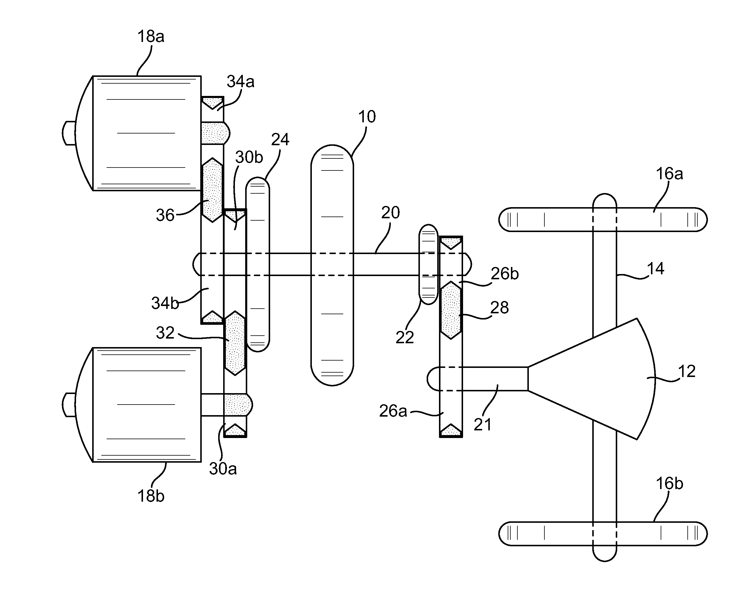
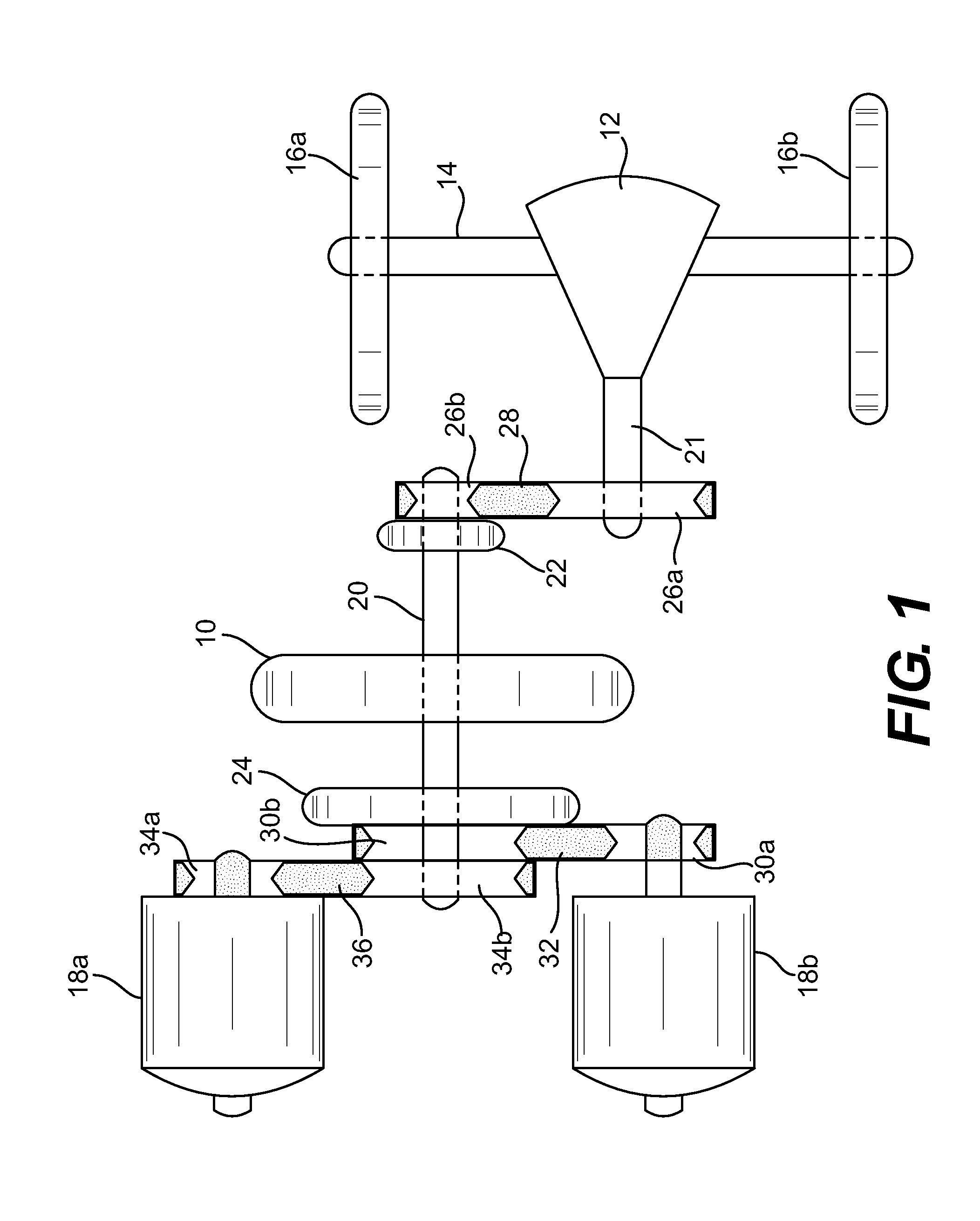
The invention is a vehicle that uses a flywheel and electric motor to propel. The vehicle has a first and second axle, with a first gearbox and first and second electrical storage devices connected to the electric motor. The flywheel is selectively connected to the first gearbox through a clutch. The vehicle also has one or more auxiliary electrical storage devices that are connected to the flywheel. The main and auxiliary electrical storage devices can be batteries or capacitors. The vehicle can also have a charging assembly with inverters and chargers for the batteries. The vehicle can also have a controller that determines which device powers the electric motor and which device is recharged based on the vehicle's speed and load. The vehicle can also have a direction selector to select between forward or backward propulsion. The technical effects of this invention include improved efficiency, reduced emissions, and improved performance and control of the vehicle's power system.

Problems solved by technology

This urgency is constantly reinforced by higher fuel prices, dwindling fuel supplies, and reports of dire environmental effects of internal combustion engine exhaust.
The difficulty is in the actual execution of the concept.
One problem is the use of a single battery or energy source that must run the motor to rotate the flywheel and be recharged.

Method used


Image

  • Energy recovery drive system and vehicle with energy recovery drive system
  • Energy recovery drive system and vehicle with energy recovery drive system
  • Energy recovery drive system and vehicle with energy recovery drive system

Examples


Embodiment Construction

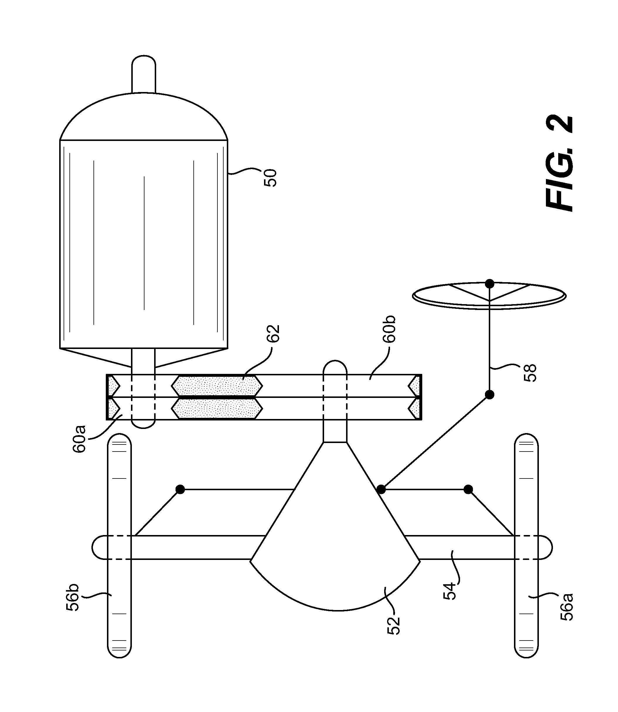
[0028]Embodiments of the invention may comprise a vehicle having an energy recovery drive system. Additionally, embodiments of the invention may comprise an energy recovery drive system, with or without the accompanying vehicle. The vehicle in embodiments of the invention may comprise any desired vehicle to which the energy recovery drive system may be affixed, including but not limited to cars, trucks, SUVs, motorcycles, buses, trains, streetcars, trolleys, agricultural vehicles (e.g., tractors, combines), and the like.

[0029]Vehicles of embodiments of the invention are propelled by an electric motor (DC or AC motor) coupled to one of the vehicle's axles. The electric motor is powered by two or more electrical storage devices (e.g., batteries or battery banks or capacitors). The electrical storage devices are charged by alternators driven by a rotating flywheel. The flywheel is selectively coupled to a different one of the vehicle axles, such that movement of the vehicle (caused by ...


PUM


Abstract

Vehicles of embodiments of the invention are propelled by an electric motor (DC or AC motor) coupled to one of the vehicle's axles. The electric motor is powered by two or more electrical storage devices (e.g., batteries or battery banks or capacitors). The electrical storage devices are charged by alternators driven by a rotating flywheel. The flywheel is selectively coupled to a different one of the vehicle axles, such that movement of the vehicle (caused by the electric motor) causes the rotation of the flywheel.

Description

CROSS-REFERENCE TO RELATED APPLICATIONS[0001]This application is a continuation of and claims priority to U.S. patent application Ser. No. 13 / 293,273, filed Nov. 10, 2011, the contents of which are incorporated herein by reference in its entirety.FIELD OF THE INVENTION[0002]The present invention relates generally to vehicles and vehicle drive systems, and more particularly to vehicles and vehicle drive systems having energy recovery capabilities.BACKGROUND[0003]The need for energy efficient and clean-running vehicles has existed for many years. This urgency is constantly reinforced by higher fuel prices, dwindling fuel supplies, and reports of dire environmental effects of internal combustion engine exhaust. Much of the popular effort directed to solving these problems includes increasing the efficiency of internal combustion engines thereby resulting in cars with greater gas mileage.[0004]One area of effort in seeking fuel efficient vehicles is in the hybrid type of cars. Generally...

Claims


Application Information

Patent Timeline
Patent Type & Authority Applications(United States)
IPC IPC(8): B60L11/18B60L50/30
CPCB60L11/1809B60L7/10B60L2240/421B60L2240/461B60K6/105B60K6/52Y02T90/14Y02T10/92Y02T10/7072B60L50/40B60L50/30B60L53/00B60L58/21B60L58/20B60L53/56Y02T10/62Y02T10/64Y02T10/70Y02T90/12
Inventor BERBARI, GEORGE EDMOND
Owner ARC ENERGY RECOVERY
Learn More