
Nuclear-Fossil Fueled Hybrid Power Generation System

a hybrid power generation and nuclear fuel technology, applied in the direction of steam generation using hot heat carriers, greenhouse gas reduction, machines/engines, etc., can solve the problems of uneconomical and/or unreliable prior art to reduce greenhouse gas and other emissions through the combination of nuclear and fossil fuels, and the overall process efficiency is limited to approximately 33 percent. , to achieve the effect of reliable electric power production, reducing greenhouse gas and other pollutants, and improving the rate of emission

Inactive Publication Date: 2014-04-03
DIMONTE MICHAEL JOHN
View PDF7 Cites 4 Cited by
  • Summary
  • Abstract
  • Description
  • Claims
  • Application Information

AI Technical Summary

Benefits of technology

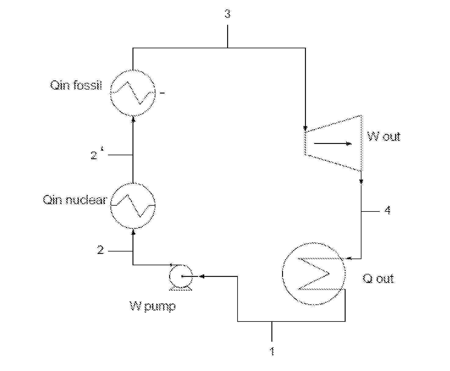
The present invention proposes the best way to set up equipment and systems in an electric power plant to produce energy efficiently with reduced harmful emissions. It recommends using a nuclear reactor as a heat source for the feed water before it becomes the working fluid by using fossil fuels. This results in a significant improvement in emissions per unit of energy produced. Additionally, the invention can be used as a way to extend the life of existing power plants, improving the economics of generating electricity through use of installed infrastructure.

Problems solved by technology

Other energy sources can emit lower levels of pollutants per unit of electric energy but all are less plentiful, reliable, and typically more costly.
Therefore there is economic inertia to continue operating these plants; however this exasperates initiatives to modernize and replace highly polluting plants with lower emission or non-polluting technologies.
Prior art to reduce greenhouse gas and other emissions through the combination of nuclear and fossil fuels are uneconomical and / or unreliable.
Therefore the overall process efficiency is limited to approximately 33 percent versus 39 percent typically achieved in fossil fueled Rankine cycle plants.
2) The referenced method is not applicable to repowering existing fossil fueled power plants and therefore does not take economic advantage of the established infrastructure of the largest fraction of existing power plants.
Other more recent hybrid energy systems which incorporate nuclear energy, such as the Gen IV Hybrid—Nuclear / Natural Gas Synfuels system by the Idaho National Laboratory, May 2011 involve complex gas reforming, methanol synthesis and related processes that make the process economically unattractive.

Method used


Image

  • Nuclear-Fossil Fueled Hybrid Power Generation System
  • Nuclear-Fossil Fueled Hybrid Power Generation System

Examples


Embodiment Construction

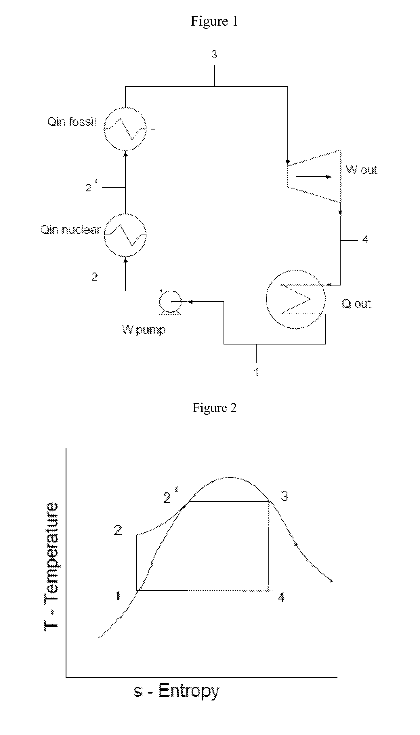
[0011]One embodiment of the invention presented herein is for application to an existing coal fired power plant employing the Rankine thermodynamic cycle. Referring to the drawings, and particularly the process diagram FIG. 1, this embodiment inserts the nuclear reactor as a heat input (Qin nuclear) to sub-cooled water 2 leaving the feed water pump (W pump). In this case sufficient heat is added to elevate the enthalpy of the water to that of a saturated liquid 2′. The saturated water is then input to the coal fired boiler which adds sufficient heat (Qin fossil) to raise the enthalpy of the water and water-steam mixture to that of a saturated vapor 3. The working fluid (steam) is subsequently directed the steam turbine (Wout) that extracts energy leaving the work fluid as a wet mixture 4. This mixture then enters the condenser (Qout) which reduces the enthalpy of the working fluid to that of a saturated liquid 1, and then directs the liquid back to the feed water pump (Wpump) in thi...


PUM


Abstract

An electric generating system employing a nuclear reactor to heat feedwater prior to fossil fueled boiler and superheater sections to economically produce electricity with reduced greenhouse gas and other polluting emissions

Description

TECHNICAL FIELD[0001]The invention is a power generating system as represented in USPTO Patent Classes: 60—Power Plants, 110—Furnaces, and 431—Combustion.[0002]More specifically this is can be widely employed as a stationary electric power generation system commonly operated by electric utility companies and industrial companies requiring electric power to operate process lines.BACKGROUND[0003]This invention relates to the economical generation of electric power from fossil fuels with reduced emissions of greenhouse gases, carbon dioxide, sulfur oxides, nitrous oxides, mercury, flue gas particulates, sludge, and other environmental pollutants. Existing electric power generating systems utilize fossil fuels, nuclear, hydroelectric, wind, solar, geothermal, and other energy sources. The dominant fuel source in the United States, China, and certain other industrialized countries is coal, which emits CO2 at a rate of approximately 900 grams per kWh (250 g / MJ). Newer gas fired combined c...

Claims


Application Information

Patent Timeline
IPC IPC(8): G21D1/00
CPCG21D1/00F01K13/00F22B1/18G21D5/16Y02E30/00
Inventor DIMONTE, MICHAEL JOHN
Owner DIMONTE MICHAEL JOHN
Learn More