
Double-sided cutting inserts with Anti-rotation features

Active Publication Date: 2014-03-27
KENNAMETAL INC
View PDF9 Cites 28 Cited by
  • Summary
  • Abstract
  • Description
  • Claims
  • Application Information

AI Technical Summary

Benefits of technology

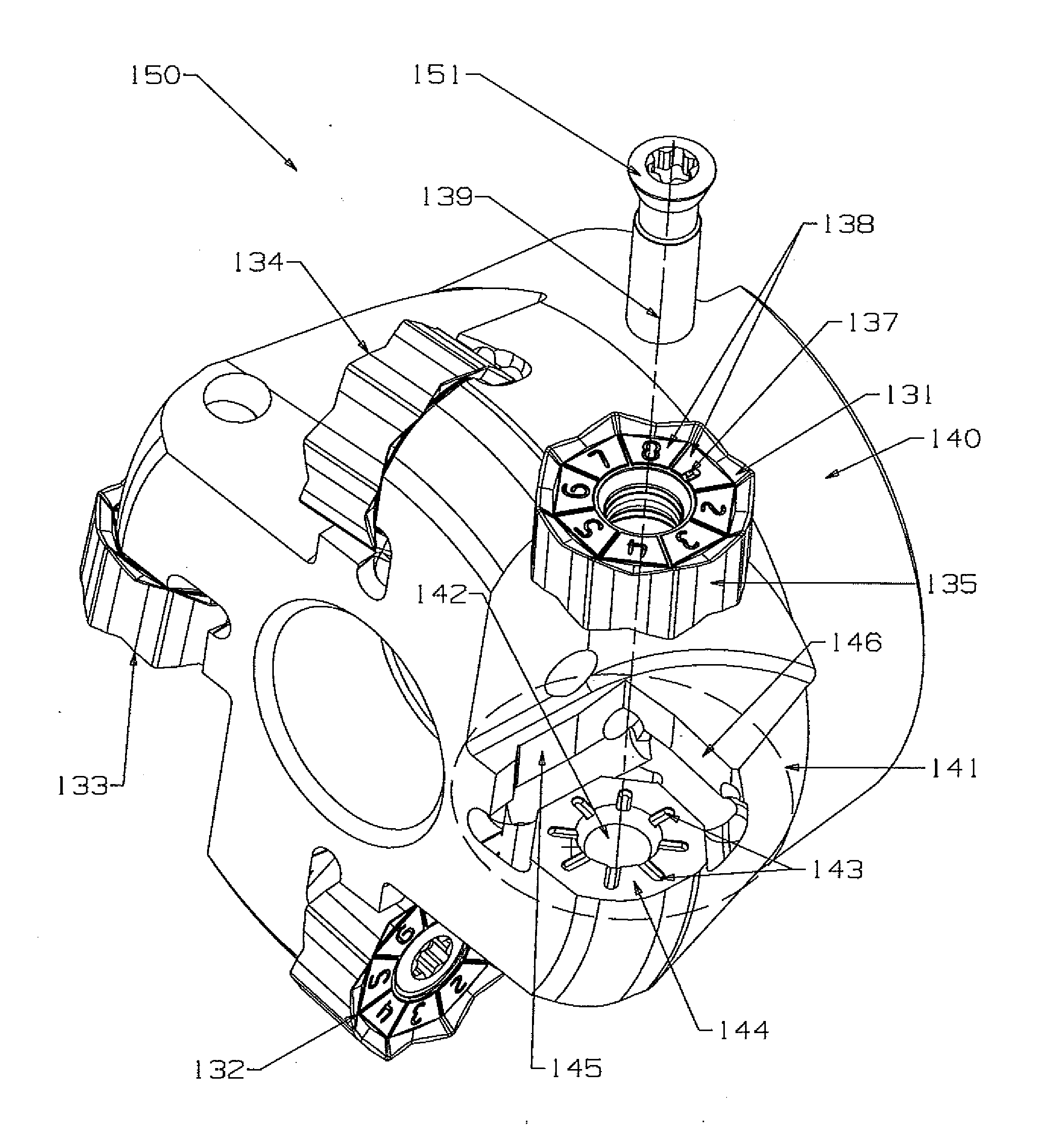
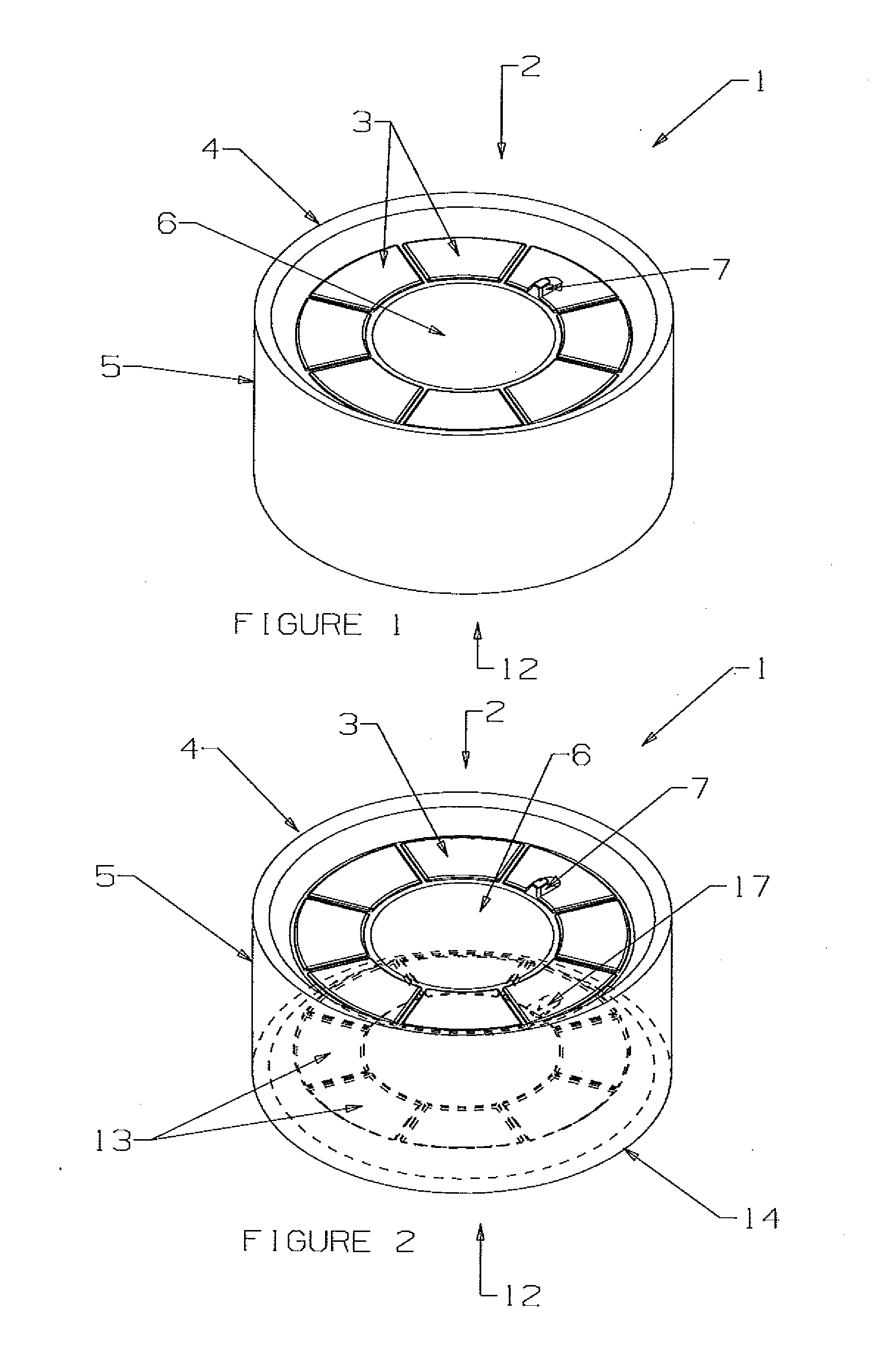
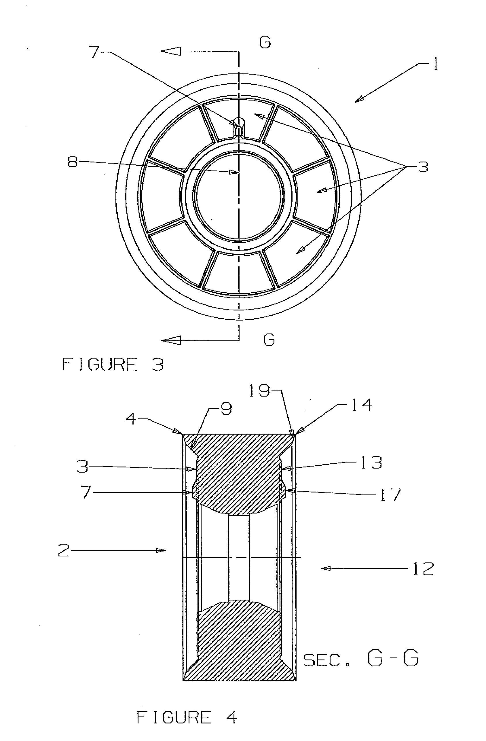
This patent is about an anti-rotation arrangement between a double-sided cutting insert and an insert receiving pocket in a tool holder. The cutting insert has anti-rotation elements on its top and bottom surfaces that fit into anti-rotation elements in the pocket to prevent the cutting insert from rotating. This arrangement ensures that the cutting edge is always in the correct position when machining metal or metal alloys, resulting in improved chip-breaking and machining efficiency.

Problems solved by technology

The cutting insert may be subjected to compressive forces, vibratory forces, and / or rotational torque during machining operations.
Due to the compression, vibration, rotation, and / or improper indexing of the cutting insert, the cutting insert may rotate within the insert receiving pocket.
The rotation of the cutting insert may result in chipping and / or cracking of the cutting insert, undesired contact between the cutting insert and the cutting tool, loosening of the fastening screw, ejection of the cutting insert from the insert receiving pocket, poor finishing, dimensional inaccuracies, and / or excessive tool wear.

Method used


Image

  • Double-sided cutting inserts with Anti-rotation features
  • Double-sided cutting inserts with Anti-rotation features
  • Double-sided cutting inserts with Anti-rotation features

Examples


Embodiment Construction

[0034]The present disclosure describes features, aspects, and advantages of various non-limiting embodiments of cutting inserts and cutting tools. It is understood, however, that this disclosure also embraces numerous alternative embodiments that may be accomplished by combining any of the various features, aspects, and / or advantages of the various non-limiting embodiments described herein in any combination or sub-combination that one of ordinary skill in the art may find useful. Such combinations or sub-combinations are intended to be included within the scope of this specification. As such, the claims may be amended to recite any features or aspects expressly or inherently described in, or otherwise expressly or inherently supported by, the present disclosure. Further, Applicants reserve the right to amend the claims to affirmatively disclaim any features or aspects that may be present in the prior art. Therefore, any such amendments comply with the requirements of 35 U.S.C. §112...


PUM

PropertyMeasurementUnit
Angleaaaaaaaaaa
Angleaaaaaaaaaa
Areaaaaaaaaaaa

Abstract

A double-sided cutting insert may generally comprise a top surface, a bottom surface, at least one side surface interconnecting the top surface and the bottom surface and forming at least one cutting edge, a through hole extending between the top surface and bottom surface, wherein each of the top surface and bottom surface comprise at least one anti-rotation element. The cutting insert may comprise a single anti-rotation element on the top surface and a single anti-rotation element on the bottom surface. The anti-rotation element may be proximate to the through hole. A cutting tool using the cutting inserts, as well as methods of making and using the same are also described.

Description

BACKGROUND OF THE TECHNOLOGY[0001]1. Field of Technology[0002]The present disclosure generally relates to cutting inserts and cutting tools including the cutting inserts. The present disclosure more particularly relates to double-sided cutting inserts comprising features to prevent rotation of the cutting inserts when mounted to a cutting tool.[0003]2. Description of the Background of the Technology[0004]Cutting inserts used in machining of metals and metal alloys may be mounted in an insert receiving pocket of a tool holder for a cutting tool. The cutting insert may be secured in the insert receiving pocket by, for example, a fastening screw inserted through a hole in the cutting insert in an orientation to present a cutting edge of the cutting insert to a workpiece. The cutting insert may be indexable such that the cutting insert is configured to be rotated or otherwise repositioned in the insert receiving pocket by the operator to expose a new cutting edge when a cutting edge in ...

Claims


Application Information

Patent Timeline
IPC IPC(8): B23C5/22B23B27/22B23B27/16
CPCB23C2200/045B23C2200/161B23C2200/168B23C2210/168B23C2210/66Y10T407/2266Y10T407/235Y10T407/23Y10T409/303752Y10T407/2274B23C5/2213
Inventor FANG, X. DANIELDUFOUR, JEAN-LUCWILLS, DAVID J.
Owner KENNAMETAL INC
Learn More