Connectors manufactured by three-dimensional printing

Inactive Publication Date: 2014-03-27
A RAYMOND & CO
View PDF1 Cites 35 Cited by
  • Summary
  • Abstract
  • Description
  • Claims
  • Application Information

AI Technical Summary

Benefits of technology

The present invention is a new connector and method that has advantages over traditional devices. It saves money and time by not requiring special tooling or dies. It also allows for quick and inexpensive design changes and part revisions. Connectors produced using the present method have high tolerance variations, resulting in identical connectors being produced in a single manufacturing cycle. The present method is also efficient in manufacturing multiple connectors simultaneously. It reduces post-manufacturing assembly by creating mating parts in a pre-assembled condition and can integrally create and attach internal seals without requiring expensive and variable post-manufacturing assembly. Overall, the present invention provides a faster, more cost-effective, and more efficient way to manufacture connectors.

Problems solved by technology

These traditional manufacturing processes, however, disadvantageously require very expensive machined steel dies, which are difficult and time consuming to modify if part revisions are desired, and are subject to problematic part-to-part tolerance variations.
Such variations are due to molding shrinkage during curing, molding pressure differences, part warpage due to internal voids and external sink marks, and the like.
The expense of this traditional die tooling makes lower volume production of polymeric parts prohibitively expensive.
These parts are extremely slow to produce and impractically brittle.

Method used


Image

  • Connectors manufactured by three-dimensional printing
  • Connectors manufactured by three-dimensional printing
  • Connectors manufactured by three-dimensional printing

Examples


Embodiment Construction

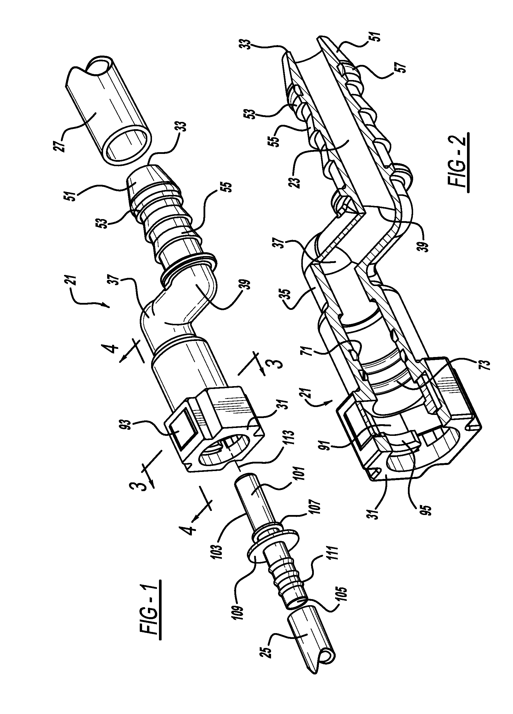
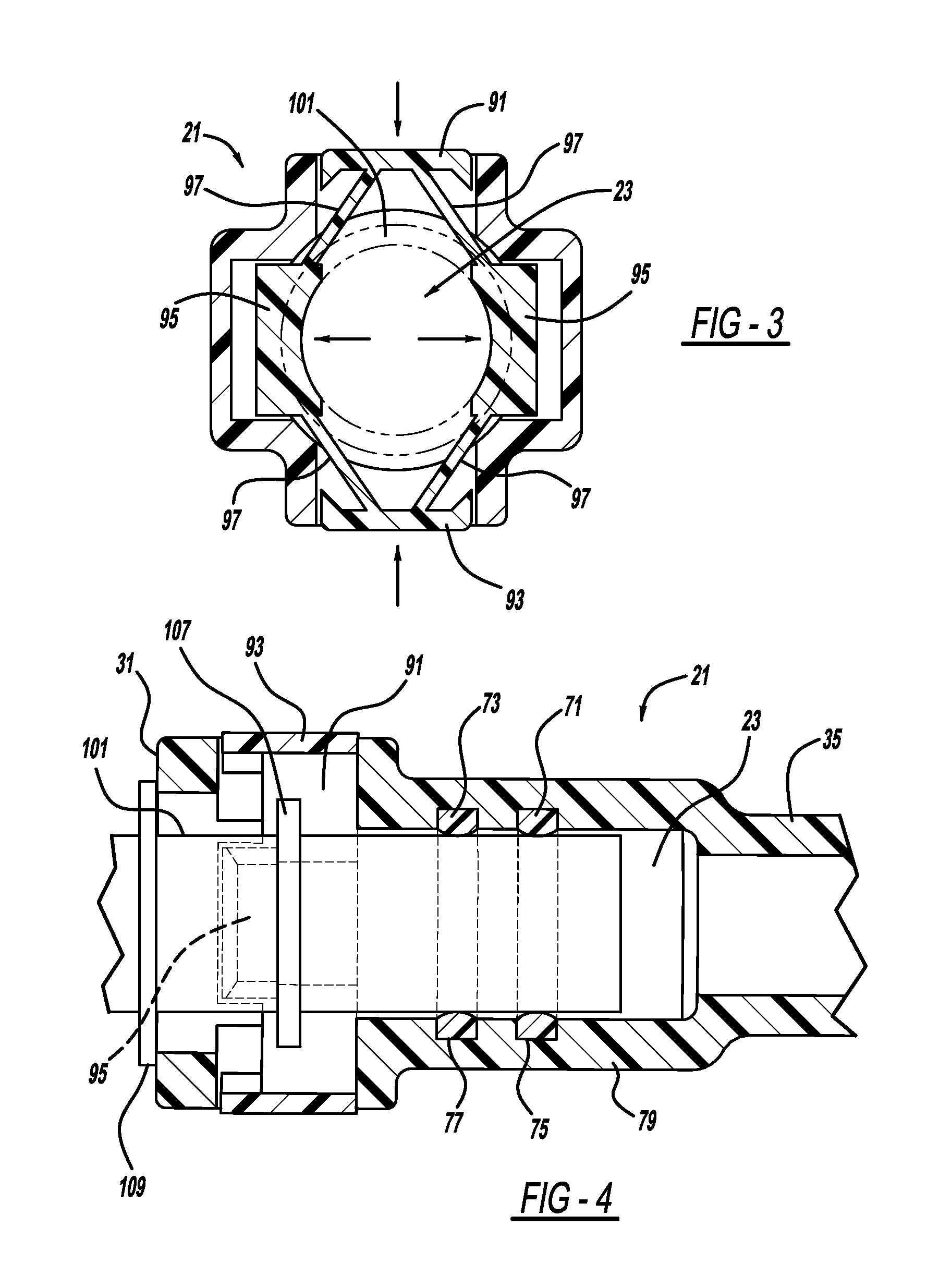
[0015]A first preferred embodiment conduit, and more particularly a quick connector 21, operable to carry a fluid through a hollow bore 23 therein is illustrated in FIGS. 1-4. For example, connector 21 can be employed in an automotive vehicle to connect multiple air conditioning, brake fluid or fuel tubes wherein the liquid or gaseous fluid flows through bore 23 bridging between the coupled tubes. Connector 21 may also be employed in industrial, laboratory or residential buildings to connect tubes carrying water, air or other fluids therebetween. Exemplary tubes 25 and 27 are shown in FIG. 1, and the term “tube” as used herein should be construed in the broadest reasonable manner and is preferably a flexible, hollow and elongated polymeric member but can alternately be a rigid polymeric, metallic or composite pipe or the like.

[0016]Connector 21 includes an enlarged female end 31 and a reduced male end 33. An elongated middle or body 35 extends between ends 31 and 33. A section at ma...


PUM

PropertyMeasurementUnit
Pressureaaaaaaaaaa
Massaaaaaaaaaa
Forceaaaaaaaaaa

Abstract

A hollow conduit is provided. In another aspect, a quick connector, suitable to carry fluid therethrough, is made of layers of material, a light curable material and / or multiple built-up materials. Another aspect uses a three-dimensional printing machine to emit material from an ink jet printing head to build up a conduit.

Description

CROSS-REFERENCE TO RELATED APPLICATIONS[0001]This application is a continuation of International Patent Application Serial No. PCT / US2012 / 039432, filed on May 24, 2012, which claims priority to U.S. Provisional Patent Application Ser. No. 61 / 492,498, filed on Jun. 2, 2011, both of which are incorporated by reference herein.BACKGROUND AND SUMMARY[0002]The present invention relates generally to conduits and more particularly to manufacturing of a fluid carrying connector.[0003]Traditionally, polymeric parts are made by injection or extrusion molding. In such processes, a heated polymeric liquid is inserted into match metal dies under high pressure, after which the dies are internally cooled in order to cure the manufactured parts. Air is vented from the die cavity when the molten polymer is injected therein. Injection and extrusion molding are ideally suited for high volume production where one hundred thousand or more parts per year are required. These traditional manufacturing proce...

Claims


Application Information

Patent Timeline
IPC IPC(8): B29C67/00F16L37/02F16L21/00
CPCB29C67/0059F16L37/02F16L21/00B29C64/124B29C64/112B29C64/106F16L37/0982B33Y80/00B33Y10/00B29C64/118
Inventor HEMINGWAY, TODD L.JACKSON, NICHOLAS
Owner A RAYMOND & CO
Why Eureka
Try Eureka