
Vestibular prosthesis

a prosthesis and vestibular technology, applied in the field of prosthesis, can solve the problems of reducing balance capacity, unable to make posture adjustments on its own, and posing a serious health hazard, so as to prevent a fall and prevent a fall

Inactive Publication Date: 2014-03-20
BENEMI12RITA UNIV AUTI12NOMA DE PUEBLA
View PDF1 Cites 12 Cited by
  • Summary
  • Abstract
  • Description
  • Claims
  • Application Information

AI Technical Summary

Benefits of technology

The invention provides a vestibular prosthesis that can send electrical signals based on the intensity of the mechanical stimulus caused by the acceleration of the head, to prevent falls. The device can calculate and transform information quickly to ensure that the stimulation of the vestibular nerves is timely and effective.

Problems solved by technology

Due to the fact that the vestibular apparatus provides this information regarding the head, it cannot make posture adjustments on its own.
The diminished balance capacity, often considered in senior adults, poses a serious health hazard due to a greater probability of falling down.
Vestibular alterations cause blurry or double vision, balance difficulties and the spatial symptoms of disorientation, vertigo, postural imbalance, nausea, vomit, among others, which are often signs of a vestibular system dysfunction.
Symptoms can be mild or very severe and long lasting, resulting in total disability with a subsequent high economic cost.
Therefore, a 10-20-millisecond delay in the output signal of the vestibular apparatus (because of deterioration due to old age or because of a vestibule-specific pathology) leads to an unavoidable (uncontrollable) fall.
The second cause of the uncontrollable fall is the quantitative change in the output signal, such as the loss of information of the otolithic organ or the semicircular canal, for example.
The balance problems associated to this disease are produced due to an alteration in the inner ear's fluids with an endolymph accumulation).
However, surgery normally means having to give up the capacity to hear in the affected ear with the purpose of stopping vertigo.

Method used


Image

  • Vestibular prosthesis
  • Vestibular prosthesis
  • Vestibular prosthesis

Examples


example

Vestibular Galvanic Stimulation (VGS)

Results

[0130]The stimulator used is a current amplifier known as bridge H (see FIG. 6). When using a 9 V battery and a 0-50 KΩ precision potentiometer at the input, a current range at the output ranging between 0.2 to 1.3 mA is obtained. When using a 9 V battery and a 0-50 KΩ precision potentiometer, a current range at the output ranging between 0.2 to 1.3 mA is obtained. The electrodes consist of two 5-mm diameter silver chloride circular pieces adhered to the subject's mastoid region.

[0131]A VGS stimulation test was carried out in 13 healthy subjects, women and men, from 20 to 35 years old. From these, 7 received bilateral bipolar stimulation while they walked, 3 received monaural bipolar stimulation while they walked, 2 received bilateral bipolar stimulation while they remained standing and 1 monaural bipolar while he remained standing. The observations in both forms yield the following results A, B and C, shown in FIGS. 7A, 7B and 7C.

From whi...


PUM


Abstract

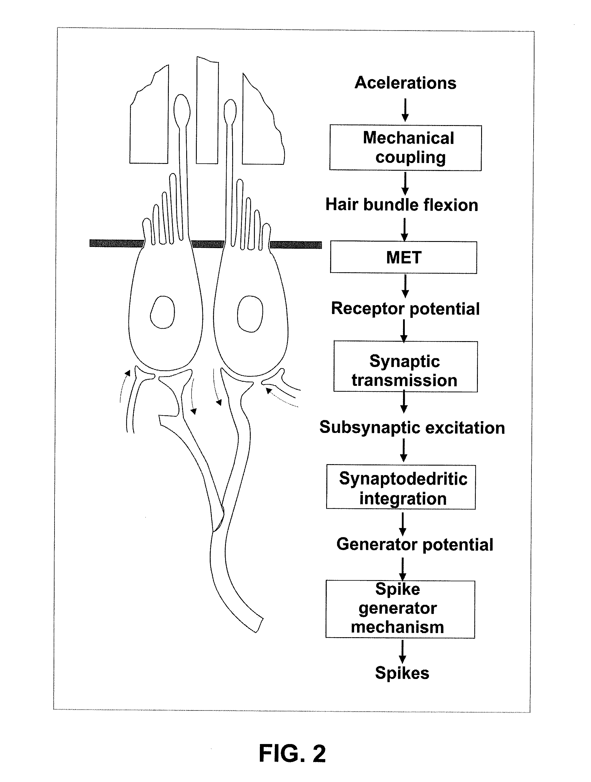
A vestibular prosthesis includes micro-electric-mechanical (MEMS) sensors, gyroscopes in each sensitivity axis (X, Y, Z), accelerometers in each sensitivity axis (X, Y, Z) to detect an angular and linear movement providing displacement measurements, gyroscopes in each one of the spatial axes (X, Y, Z), a microprocessor connected to the MEMS sensors and producing an electric pulse pattern or a continuous galvanic current pattern, a conditioning unit that amplifies and conditions the microprocessor output to apply current to the stimulation electrodes, the microcontroller being configured to determine the displacement of the cupula and the otolithic mass, determine a membrane potential as a result of a displacement detected by the MEMS sensors by means of determining a transduction current, and determine an action potential discharge pattern for the primary afferent neuron, which synapses with the hair cell by means of a mathematical model of the informative process of the vestibular mechanoreceptor.

Description

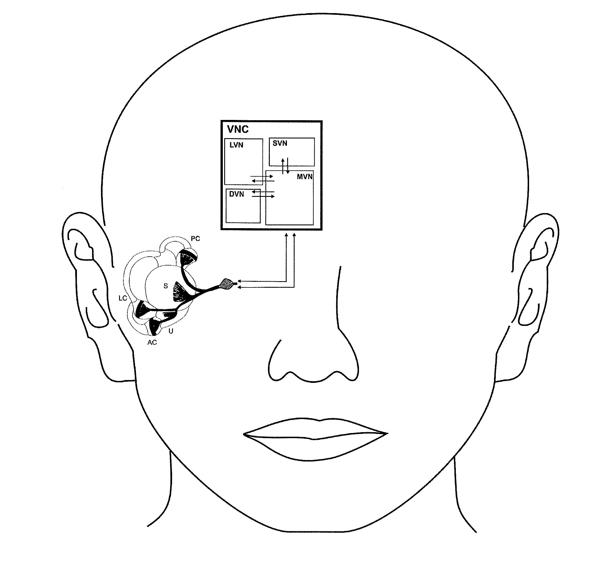
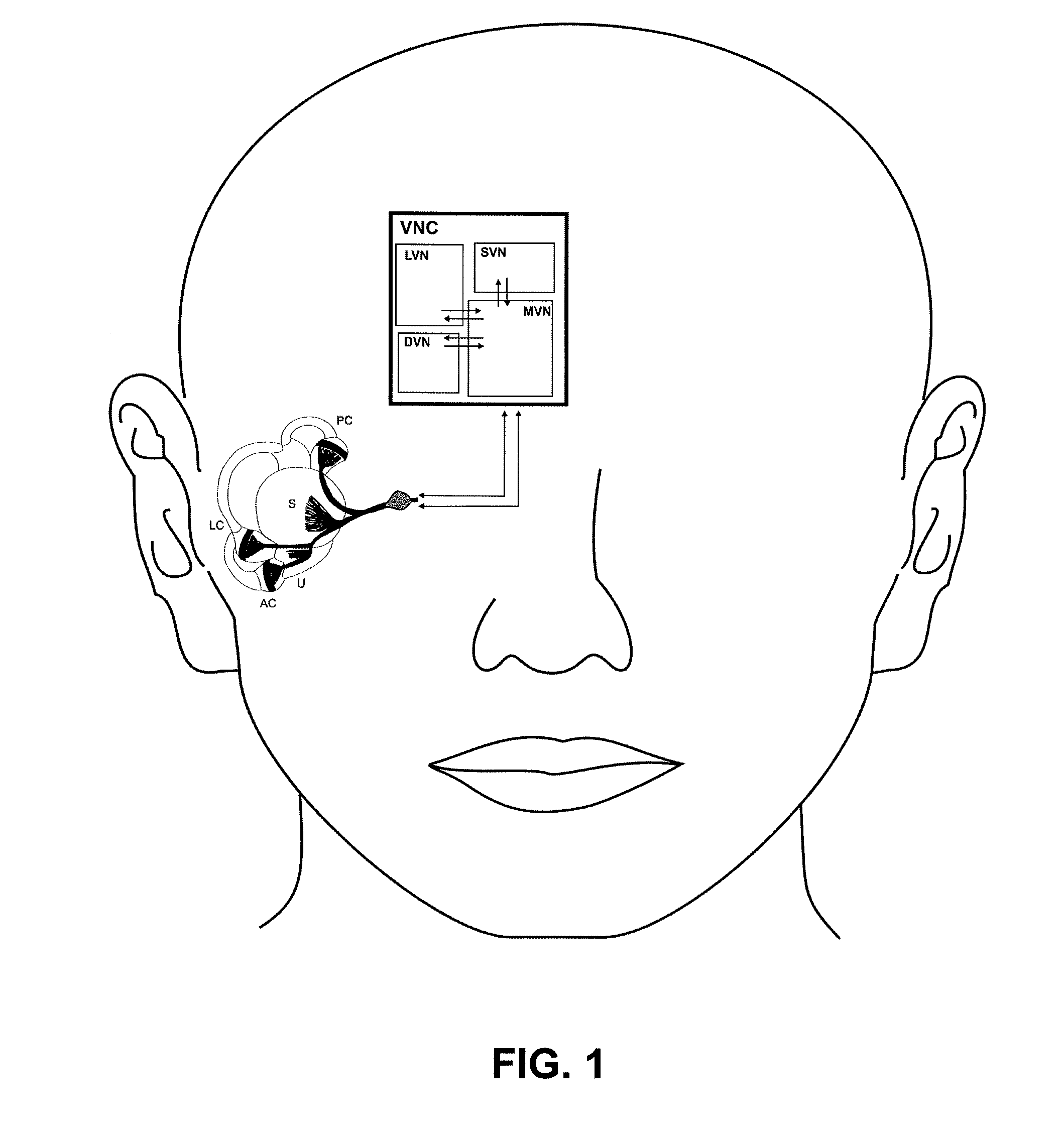
BACKGROUND OF THE INVENTION[0001]1. Technical Field of the Invention[0002]Aspects of the present invention relate to prosthesis for people that suffer from peripheral vestibular disorders. In particular, aspects of the invention relate to a vestibular prosthesis that uses a neuromimetic model of the vestibular function.[0003]2. General Background of the Invention[0004]The peripheral vestibular apparatus resides in the inner ear and is located in the interior of the temporal bone in the bony labyrinth at the base of the cranium. This apparatus is responsible for the transduction of movement during changes in the dynamics of the primary vestibular neurons; the central vestibular nuclei comprise a group of neurons from the brainstem that are responsible of receiving, integrating and distributing the information controlling a set of motor activities, such as the movement of the eyes and the head; postural reflexes, autonomic reflexes and the generation of a spatial framework of the subj...

Claims


Application Information

Patent Timeline
IPC IPC(8): A61N1/372
CPCA61N1/0526A61N1/3606A61N1/36125A61N1/36171A61N1/36175A61N1/36178
Inventor EGUIBAR, ENRIQUE SOTOGUADALUPE VEGA Y. SAENZ DE MIERA, MARIA DEL ROSARIOALEXANDROVA, TAMARAALEKSANDROV, VLADIMIRROMERO, MARIBEL REYESCARRILLO, ADRIANA CRISTINA PLIEGOGUERRERO SANCHEZ, WUIYEVALDO FERMIN
Owner BENEMI12RITA UNIV AUTI12NOMA DE PUEBLA
Learn More