Stretch-blow molding machine

a molding machine and bending technology, applied in the direction of auxillary shaping apparatus, manufacturing tools, ceramic shaping apparatus, etc., to achieve the effect of easy absorption of even high forces

Active Publication Date: 2014-03-20
KRONES AG
View PDF2 Cites 12 Cited by
  • Summary
  • Abstract
  • Description
  • Claims
  • Application Information

AI Technical Summary

Benefits of technology

[0007]One aspect of the present disclosure disclosure is to provide a stretch-blow molding machine of the type mentioned above which comprises inexpensive and universally applicable equipment, and to provide a method of stretch-blow molding containers by which idle times in the process flow can be reduced to a minimum or completely avoided.
[0008]The electronic control unit of the blow molding station can be inexpensively and universally utilized in different blow molding machines which differ, for example, in different stretching rod drive systems. This inexpensive and universally usable control unit can at least partially compensate the additional costs of equipment for electric stretching (philosophy of same parts with respect to the control unit).
[0009]According to the method, the idle time in the production operation is drastically reduced or completely eliminated, as the movement of the stretching rod is started already during the locking phase of the blow mold or at the latest with the beginning of the locking phase, so that the stretching rod is positioned at the preform bottom, or very close, for example only 1 mm, in front of the preform bottom, or even already performs pre-stretching before the blow nozzle is placed onto the preform mouth in a sealing manner. It is even conceivable in the method to have the stretching rod immerse in the preform already before the locking phase is started, for example as of the point in time at which a transfer arm with the preform enters the path section it has in common with the blow molding station or the blow mold, respectively. This means further saving of idle time and also permits to moderately control the rate of movement of the stretching rod because a relatively long period can be utilized to bring the free end of the stretching rod close to the preform bottom or into contact with the preform bottom, or to even pre-stretch the preform. This control of the stretching rod movement is particularly conveniently performed with the electric servomotor which accomplishes the positioning depending on the type of preform. The stretching rod can be initially very quickly accelerated and then decelerated to stretching speed by means of the electric servomotor, or for approaching it to the preform bottom, it can temporarily perform a very quick moving phase. This individual speed control of the stretching rod, conditioned by the performance of the electric servomotor, saves process time and nevertheless does not involve any hazard for the preform or the blow mold. The preform length or the stretching rod stroke until it comes into contact or nearly into contact with the preform bottom is read out from the control unit. The movement profile of the stretching rod movement can be designed individually by the electric servomotor and the control unit. The critical stroke length of the movement of the stretching rod or the length of the preform can be automatically determined by a reference point approach, or else be manually predetermined at the control unit, for example via a touch screen, or it can be transmitted to the individual control units via a decentralized external master control system, for example within a bus system. The reduction or the elimination of the idle time results in clearly increased production rates in the production operation.

Problems solved by technology

However, it is also conceivable not to drive the stretching rod to the upper position until a later point in time.

Method used


Image

  • Stretch-blow molding machine
  • Stretch-blow molding machine
  • Stretch-blow molding machine

Examples


Embodiment Construction

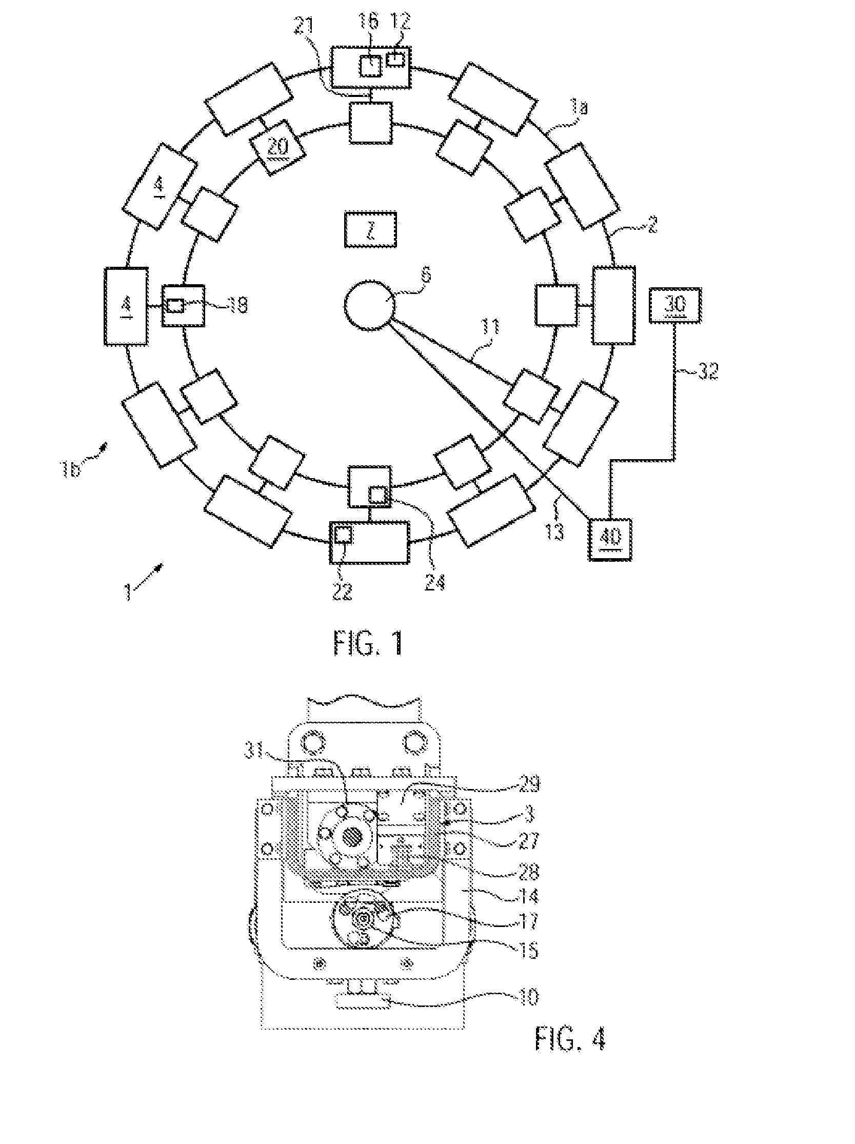
[0055]FIG. 1 schematically shows a stretch-blow molding machine 1 for stretch-blow molding containers from preforms. The stretch-blow molding machine 1 is a rotary-type machine with a blow-molding unit 2 supporting blow-molding stations 4 at its periphery which represents a part 1a rotating in relation to a stationary part 1b. The concept according to the disclosure, however, can be used without restrictions for stretch-blow molding machines in which the blow molding stations are arranged stationarily (not shown).

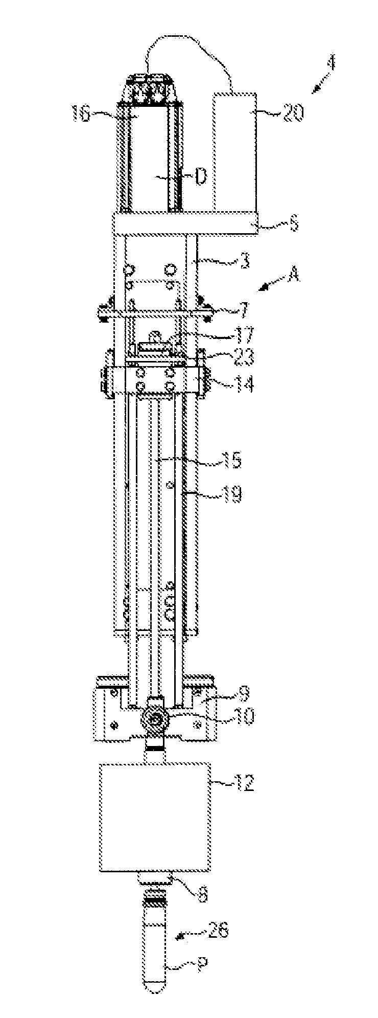
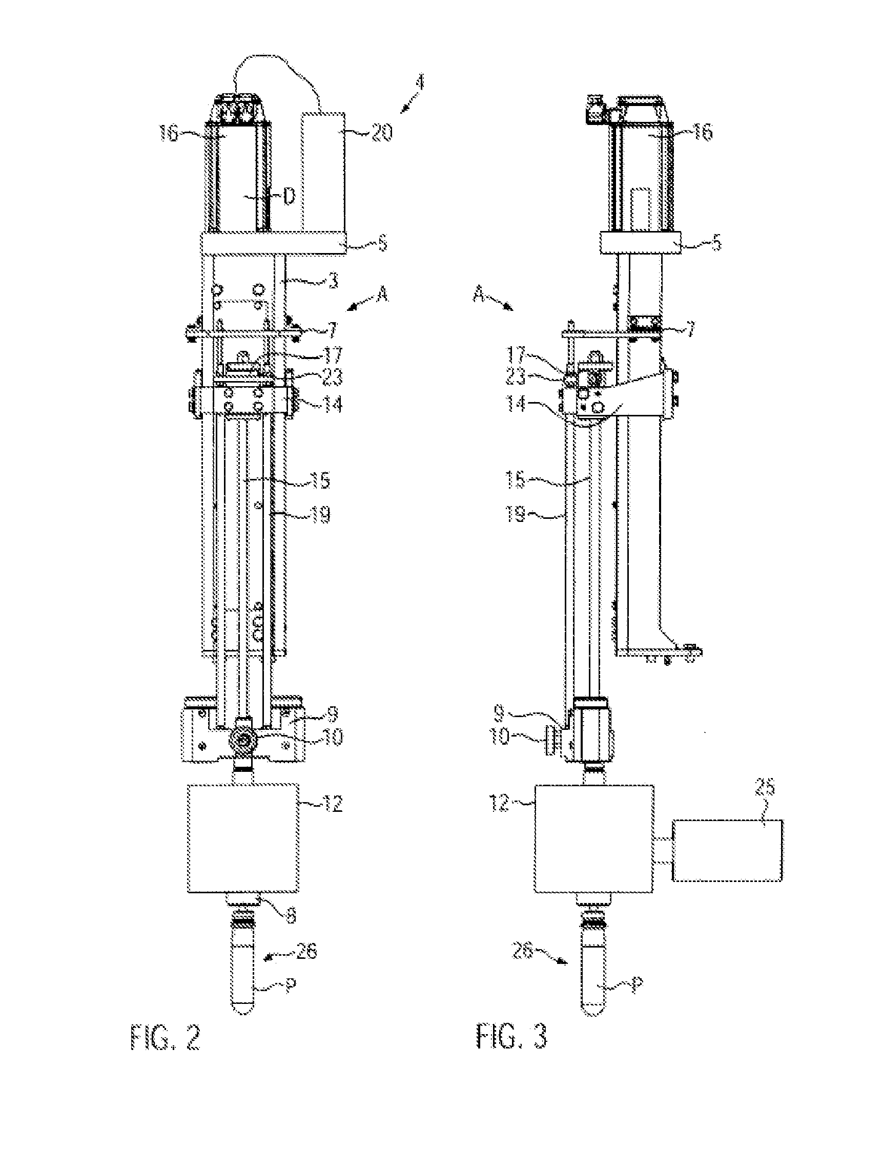
[0056]For at least one blow molding station 4, one electronic control unit 20 each is arranged on the blow-molding unit 2 in FIG. 1. The power supply of the control units 20 is accomplished e.g. via connection lines 11 and a rotary transmission leadthrough 6, e.g. a slip ring arrangement and / or a medium leadthrough, in the center of the blow-molding unit 2. Each blow molding station 4 has a stretching rod drive system, here with an electric servomotor 16, and a valve sectio...


PUM

PropertyMeasurementUnit
circuit voltageaaaaaaaaaa
voltageaaaaaaaaaa
circuit voltageaaaaaaaaaa

Abstract

A stretch-blow molding machine having at least one blow molding station, in which a split blow mold, an adjustable blow nozzle with a valve section, a stretching rod with a stretching rod drive system, and an electronic control unit are provided, the electronic control unit arranged in the blow molding station is equipped with hardware and software for selectively operating the blow molding station with a combination of a cam drive and a pneumatic drive, or a combination of an electric servo drive and a pneumatic drive, or only an electric servo drive in the stretching rod drive system. The movement of the stretching rod is initiated in the stretch-blow molding machine in the production process of a container by means of an electric servomotor with the beginning of or during the locking phase of the blow mold and before the blow nozzle is placed, and the stretching rod is already displaced to a position in which the stretching rod is either very closely approached to the preform bottom or contacts the preform bottom, or has even already pre-stretched the preform, until the blow nozzle is placed.

Description

CROSS-REFERENCE TO RELATED APPLICATION[0001]The present application is a divisional of U.S. patent application Ser. No. 13 / 093,001 filed Apr. 25, 2011, which claims the benefit of priority of German Patent Application No. 102010028255.3 filed Apr. 27, 2010. The entire text of each of the US and the German priority applications is incorporated herein by reference.FIELD OF THE DISCLOSURE[0002]The disclosure relates to a stretch-blow molding machine as well as to a method of stretch-blow molding containers.BACKGROUND[0003]In the stretch-blow molding machine known from DE 10 2008 012 757 A (rotary machine), an electronic control unit in the rotating part is associated to each blow molding station and controls the stretching rod movement as well as the blow pressure and valve control to be able to quickly adapt the control for the production process when the product is changed. The control units in the rotating part are linked via a bus system and connected to a master control device out...

Claims


Application Information

Patent Timeline
Patent Type & Authority Applications(United States)
IPC IPC(8): B29C49/12
CPCB29C49/12B29C49/32B29C49/42B29C49/78B29C49/06B29C49/1202B29C49/1222B29C49/1229B29C49/123B29C49/42378B29C49/4238B29C2949/0715B29C2049/7834B29C2049/7879
Inventor FINGER, DIETERGELTINGER, FLORIANSCHNEIDER
Owner KRONES AG
Why Eureka
Try Eureka