
Separation of oil droplets from water

a technology of oil droplets and water, applied in the field of oil droplets separation, can solve the problems of difficult removal, difficult separation of small droplets, and difficult separation of water droplets

Inactive Publication Date: 2014-03-20
SCHLUMBERGER TECH CORP
View PDF8 Cites 8 Cited by
  • Summary
  • Abstract
  • Description
  • Claims
  • Application Information

AI Technical Summary

Benefits of technology

The patent text describes a treatment process for water containing oil droplets. The process involves using a surface with areas of different surface energy, which allows oil droplets to adhere to the surface and form a contact angle greater than 90°. The oil droplets can then be collected and separated from the water. The treatment process can be applied to saline aqueous solutions containing oil droplets, and it can lead to the separation of oil droplets or the coalescence of small droplets to larger ones that can be more easily separated. The technical effect of this treatment process is the efficient removal of oil droplets from water without the need for a completely oil-coated surface.

Problems solved by technology

However, the water which is separated from the oil generally contains very small droplets of oil.
Because of their small size they are very slow to separate from water and it is very difficult to remove them.
However, separation of small droplets is even more difficult when working within the constraints of an underground location accessed by a wellbore.
Because small droplets can adhere to the surface but cannot coalesce to the point of forming a film, and because droplet coalescence has an upper limit, the surface can be used to collect small droplets which are hard to remove from water without the surface becoming completely coated with oil which could in turn lead to it becoming inoperative.
Eventually droplets will grow too large to continue to adhere.

Method used


Image

  • Separation of oil droplets from water
  • Separation of oil droplets from water
  • Separation of oil droplets from water

Examples


example 2

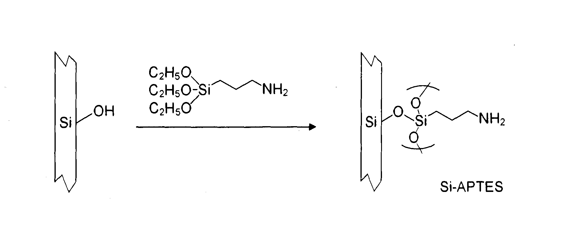
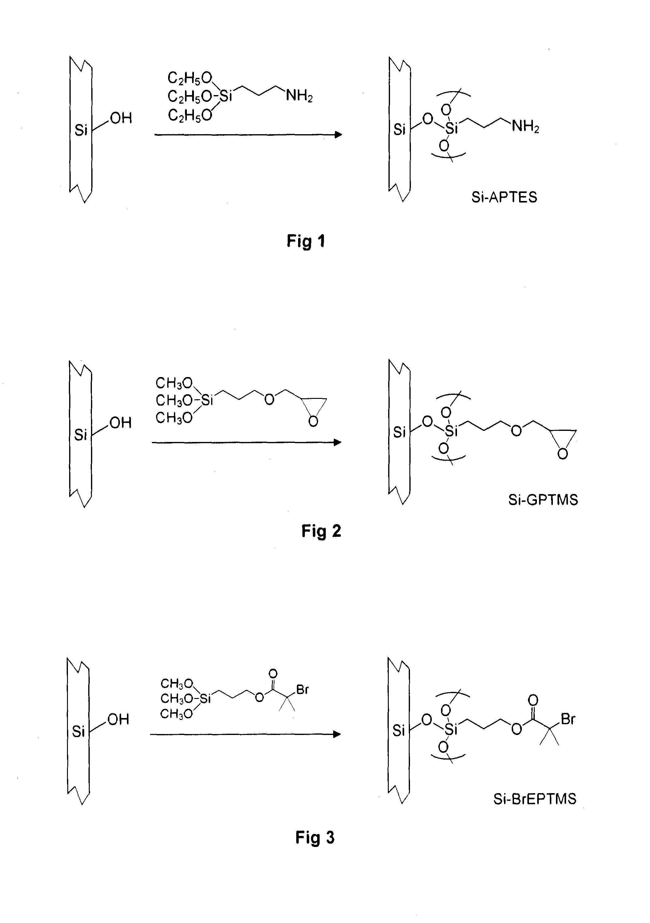
[0056]The procedure of Example 1 was repeated using four more reagents which included trialkoxy silyl groups. Each of these reagents included a hydrophobic group which became attached to the silicon wafer. The reagents were:

[0057]As in Example 1 a water droplet was placed on the surface of each coated silicon wafer, with the wafer exposed to air, and the contact angle was noted.

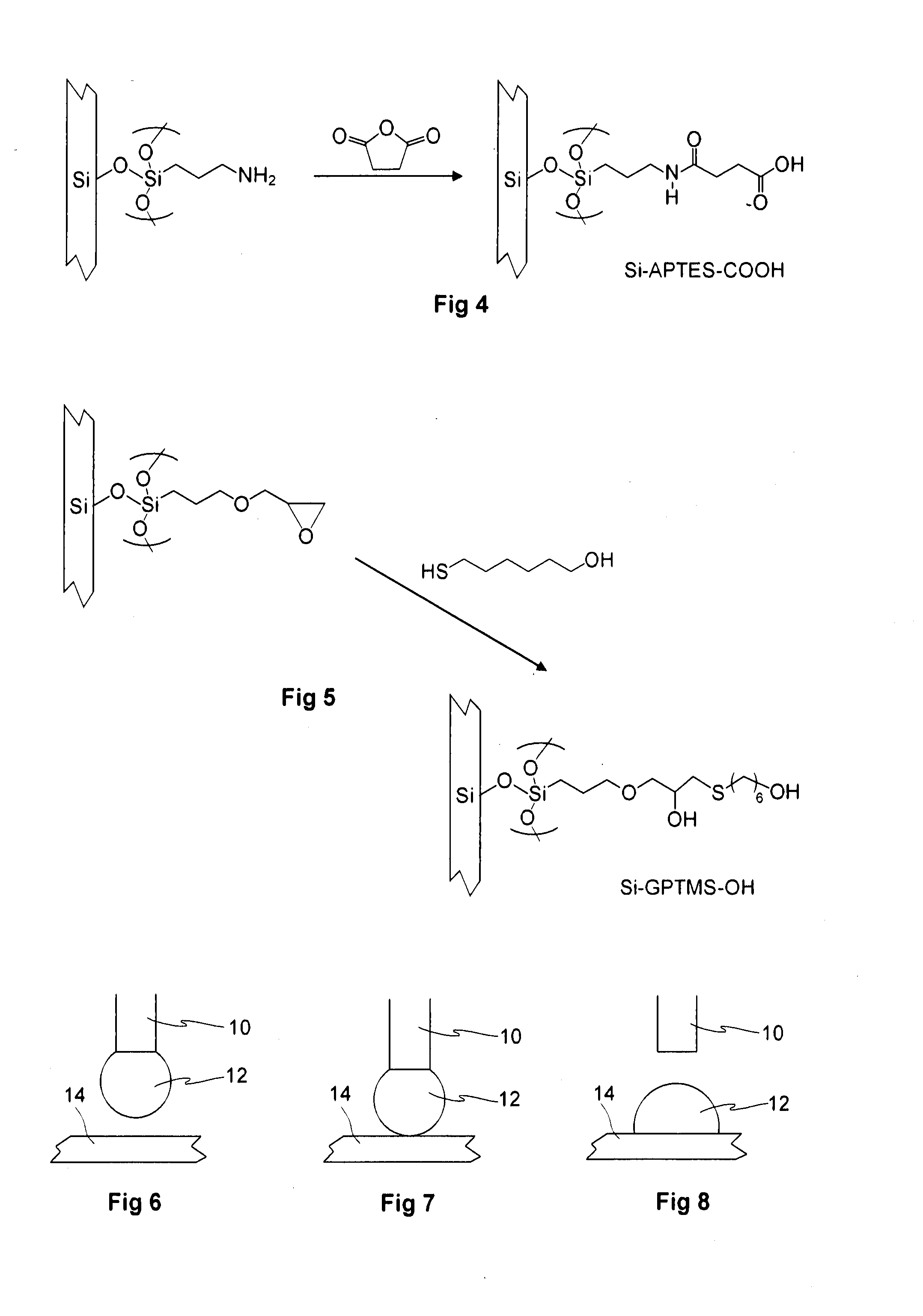
[0058]Underwater adhesion of decane droplets was examined as in Example 1 with each coated silicon wafer immersed, in a horizontal position, in de-ionised water at 20° C. The following results were obtained

Underwater adhesion of oilMonolayerWater contact angle in airdroplet (& contact angle)Si-propyl50°NoSi-phenyl60°NoSi-octadecyl81°NoSi-PFOTS113° Adheres; contact angle 34°

[0059]In the case of the Si-PFOTS wafer which had very hydrophobic fluorinated alkyl groups in the monolayer, successive further droplets of decane were added directly onto the upper surface of the droplet already adhering to the wafer surf...

example 3

Formation of Temperature Sensitive Polymer Brush

[0060]A polymer brush was polymerized onto a wafer bearing a monolayer of residues of 2-bromo-2-methyl propionic acid trimethoxysilanyl propyl ester (BrEPTMS). These residues served as an initiator for polymerization by atom transfer radical polymerization (ATRP), a method of polymerisation which leads to polymer chains of uniform length extending from the initiator sites.

[0061]The monomers for this ATRP were a mixture of

and di(ethylene glycol)methyl ether methacrylate (MEO2MA) which has the same general formula but m=2. Polymerisation is a reaction of the methacrylate groups to form a polymer chain of aliphatic carbon atoms with the ethoxy groups of the monomers in side chains. The procedure for such polymerization, as given in the supplementary information to Jonas et al in Macromolecules vol 40 pages 4403-4405 (2007), was as follows.

[0062]For a MEO2MA:OEGMA molar ratio of 90:10, 16.94 g of MEO2MA (85.5 mmol) and 2.85 g of OEGMA (9.5...

example 4

Formation of a Heterogeneous Surface

[0066]Monolayers were applied to silicon wafers, as in previous examples, using a mixture of BrEPTMS and GPTMS in various ratios. This is illustrated by the upper portion of FIG. 11. The first stage using the mixtures of BrEPTMS and GPTMS led to a mixed layer on the silicon wafers. This layer contained BrEPTMS residues, depicted as open cups 16 in FIG. 11 which provide ATRP initiator sites and GPTMS residues depicted as triangles 18 which provide hydrophilic surface areas but do not initiate ATRP. Polymer brushes were then formed by polymerization onto the BrEPTMS residues using the same monomer mixture as in Example 2 above. As illustrated at the foot of FIG. 11, this procedure led to polymer brushes which were less dense than those in the previous Example. The polymer chains of the brush contained residues of MEO2MA depicted as open circles and residues of OEGMA depicted as filled circles. The polymer chains were spaced apart by areas in which t...


PUM


Abstract

A treatment process for an aqueous phase which contains oil droplets, possibly of 10-50 nm diameter, in aqueous flow from a hydrocyclone separator, comprises bringing the water into contact with a surface subdivided into areas of differing surface energy and affinity for oil and such that when the surface is submerged in an aqueous phase, oil droplets adhere to it with an apparent contact angle in a range from 90 to 150 degrees. Areas of the surface may reduce their affinity for oil in response to an external stimulus causing controlled release of droplets adhering to the surface. The process may be used to remove oil droplets from water produced by an oil or gas well, after downhole oil water separation or after production at a at a well head, or used to coalesce droplets in such water to a larger size to enable conventional separation.

Description

FIELD AND BACKGROUND[0001]Embodiments of this invention relate to the separation of oil and water and to the separation of small droplets of oil from water.[0002]Separation of oil and water is required in a number of areas of industry. Separation can be brought about by a mechanical separator, such as a hydrocyclone. This can separate a flowing mixture of oil and water into separate flows of oil and of water. However, the water which is separated from the oil generally contains very small droplets of oil. Diameter of such droplets is often under 100 micrometres, typically 10 to 50 micrometers. Because of their small size they are very slow to separate from water and it is very difficult to remove them. Addition of chemicals may be required to achieve separation.[0003]Separation of oil and water may be required at various stages in the course of oil production and refining operations. It is sometimes desirable to carry out a separation of oil and water below ground, as oil and water ...

Claims


Application Information

Patent Timeline
IPC IPC(8): C02F1/28
CPCC02F1/288B01D17/0202
Inventor TAN, KHOOI YEEIHUGHES, TREVORHUCK, WILHELMNAGL, MICHAELA
Owner SCHLUMBERGER TECH CORP
Learn More