
Apparatus for in-line thermally treating semi-finished products

a technology of semi-finished products and in-line thermal treatment, which is applied in the direction of lighting and heating apparatus, manufacturing tools, furniture, etc., can solve the problems of difficult access to the cooling unit, poor alignment normally obtainable between the cooling unit, and excessive dimensions, so as to achieve the effect of increasing productivity and prolonging the elongated shap

Active Publication Date: 2014-03-13
DANIELI & C OFF MEC SPA
View PDF6 Cites 3 Cited by
  • Summary
  • Abstract
  • Description
  • Claims
  • Application Information

AI Technical Summary

Benefits of technology

The present invention provides an improved in-line thermal treatment apparatus for metallurgic semi-finished products with extended elongated shape. The apparatus includes multiple treatment lines that can be automatically switched between by tally automatic line change operations, which eliminates the need for manual setup and improves safety conditions. The invention also reduces the time needed for cooling unit cleaning, maintenance, and restoring the treatment line. The outer casing of the apparatus includes holding means for automatically closing the treatment units in a closed position, further reducing the manual intervention time of the line operator.

Problems solved by technology

Such a solution determines a plurality of drawbacks, the main of which are excessive dimensions, poor alignment normally obtainable between cooling units and difficult access to the cooling units due to the linear development of the device.
However, such an apparatus, described in detail in document EP0317785, is not an optimal solution because it also displays a series of drawbacks.
One drawback is the fact that the rotation axis must also be moveable with respect to the outer casing in which the drum is accommodated in order to guarantee the correct coupling between the cooling circuit and each cooling line when the latter is arranged in operating position.
This determines both constructive complications and, once again, a non-optimal, and in all cases improvable, alignment.
However, the device in U.S. Pat. No. 5,257,511 does not solve in all the aspects the other products described above.
Indeed, in all conditions other than maintenance and cleaning, the covers of the cooling units Must be blocked in closed position.

Method used


Image

  • Apparatus for in-line thermally treating semi-finished products
  • Apparatus for in-line thermally treating semi-finished products
  • Apparatus for in-line thermally treating semi-finished products

Examples


first embodiment

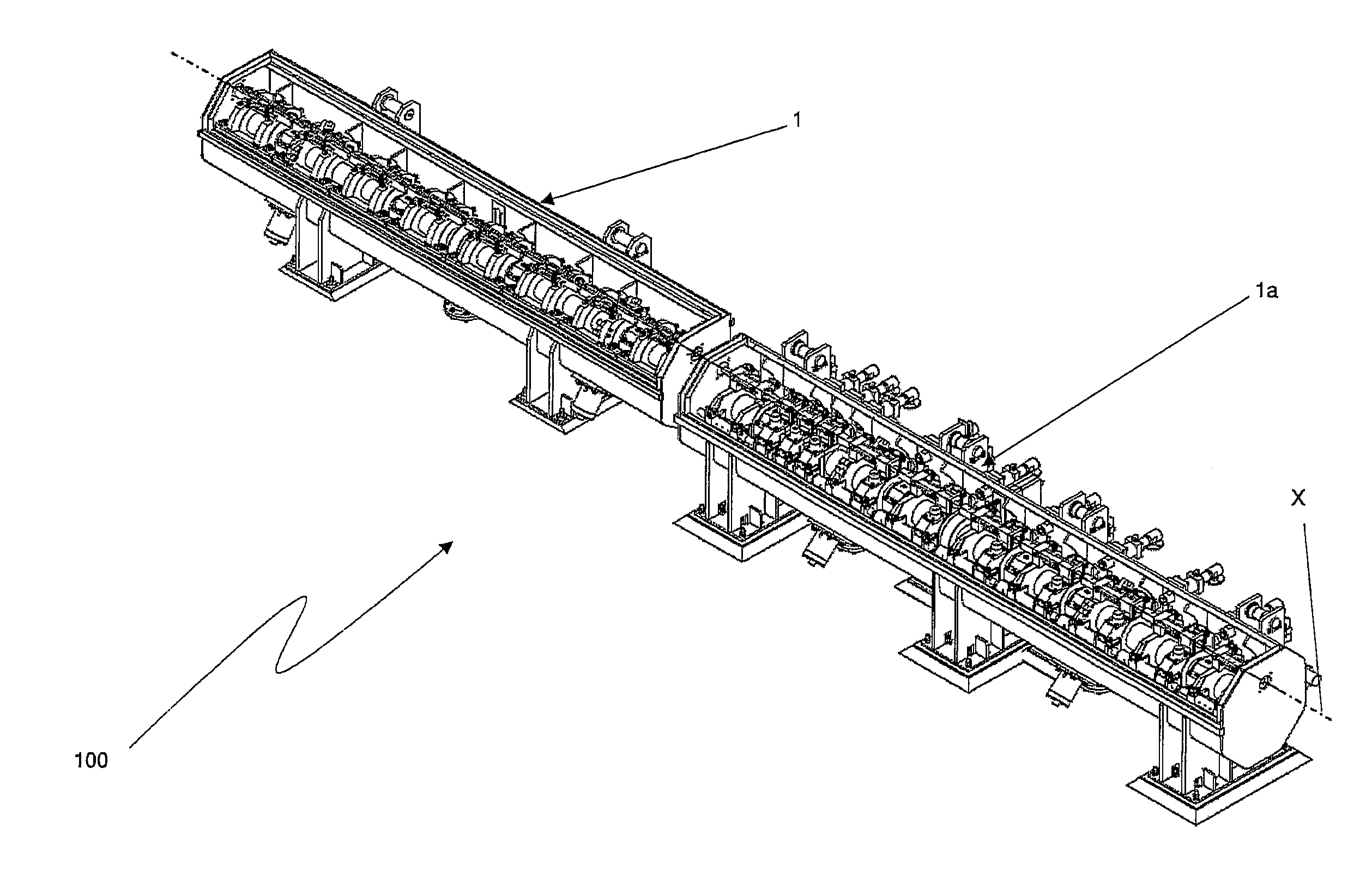
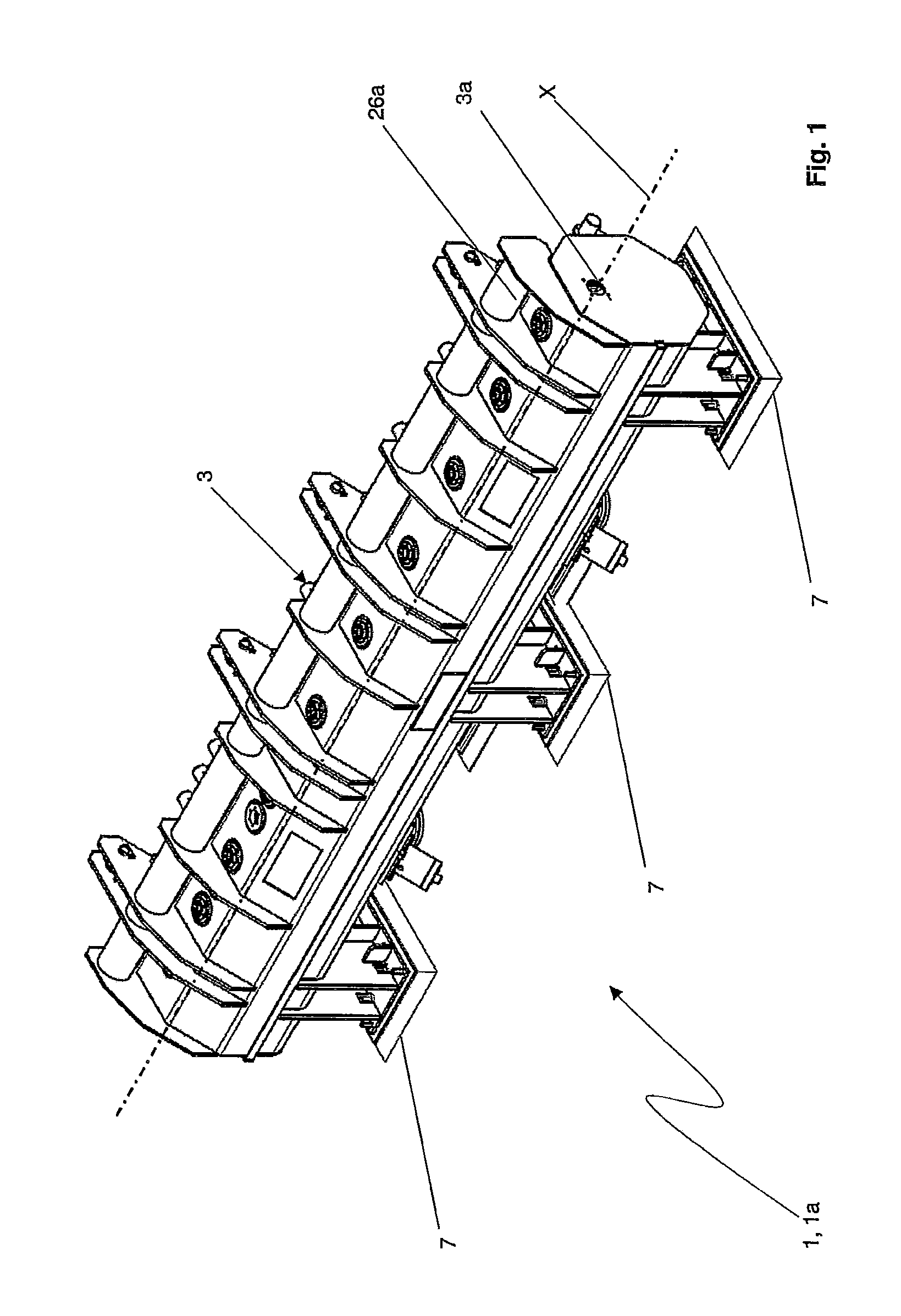
[0049]In accordance with a first embodiment shown in FIGS. 2 and 3, each of the treatment lines 6 comprises an initial guiding unit 8a, near the first opening 3a, a plurality of intermediate cooling units 8 (six cooling units 8 in the example in FIGS. 2 and 3), and a terminal guiding unit 8a, next to the second opening 3b. A pressurized cooling fluid is introduced into the cooling units 8 for carrying out a forced thermal cooling treatment on the bar 10, as described m greater detail below. A film of cooling fluid remains on the surface of the bar 10 at the outlet of the cooling units 8, to remove which, a so-called stripper unit 8b is provided immediately downstream of the cooling units 8. The same cooling fluid used in the cooling units 8 is introduced in the stripper unit 8b, but directed so as to invest the bar 10 countercurrent with respect to the crossing direction, to remove the liquid film present on the surface of the bar 10. A pair of dryer units 8c for the final drying of...

second embodiment

[0051]In accordance with the second embodiment shown in FIGS. 4 and 9, the treatment line 6 of the apparatus 1a comprises a plurality of guiding units 8d arranged in series with respect to the first and second opening 3a,b (eight guiding units 8d). In the apparatus 1a, the bar 10 is simply guided from the first to the second opening 3a,b, without undergoing any forced cooling by means of a cooling fluid but instead by exchanging heat with the guiding units 8d, so as to undergo a thermal equalization treatment.

[0052]Each of the units 8, 8a, 8b, 8c, 8d comprises a respective cylindrical through cavity 9, 9a, 9b, 9c, 9d coaxial and parallel to each other along the crossing direction X. The cavities 9a of the guiding units 8a allow to guide the bar 10 to the inlet and 10 the outlet of the cooling units 8, respectively. The cavities 9d of the guiding units 8d allow to guide the bar 10 along the entire path 2 of the apparatus 1a. The cavities 9 of the cooling units 8 are arranged to recei...


PUM

PropertyMeasurementUnit
diametersaaaaaaaaaa
angleaaaaaaaaaa
lengthaaaaaaaaaa

Abstract

An apparatus (1) for cooling a bar (10) comprising:—an outer casing (3),—a passageway (2) defining a crossing direction (X) for the bar (10),—at least one drum (4) comprising a plurality of cooling lines (6) each having at least one respective through cavity (9) parallel to the crossing direction (X) and a respective cover (15) which can move between an open position and a closed position, the drum (4) being accommodated in the casing (3) and rotational about a rotation axis (Y) to move the cooling lines (6) between an operating position (11), in which the cavity (9) is aligned with the passageway (2), and at least one resting position (12), in which the cavity (9) is separated from the passageway (2), the casing (3) being shaped so as to touch and hold the respective cover (15) in the closed position when the cooling line (6) is in the resting position (12).

Description

CROSS REFERENCE TO RELATED APPLICATIONS[0001]The present application claims priority to PCT International Application No. PCT / EP2012 / 058752 filed on May 11, 2012, which application claims priority to Italian Patent Application No. MI2011A000848 filed May 3, 2011.STATEMENT RE: FEDERALLY SPONSORED RESEARCH / DEVELOPMENT[0002]Not Applicable.BACKGROUND[0003]1. Field of the Invention[0004]The present invention relates to m apparatus tot in-line thermally treating metallurgic semi-finished products having extended elongated shape, such as bars, rods, wire rods or other semi-finished products having extended elongated shape.[0005]2. State of the Art[0006]In the technical scope of in-line processes for the production of metallurgic semi-finished products having extended elongated shape, it is known the use of thermal treatment apparatuses, in particular for cooling the semi-finished products, typically arranged downstream of a step of machining by plastic deformation, e.g. rolling. Such appar...

Claims


Application Information

Patent Timeline
Patent Type & Authority Applications(United States)
IPC IPC(8): B21B45/02
CPCB21B45/0215B21B45/0224
Inventor BORDIGNON, GIUSEPPEPOLONI, ALFREDOZERAJIC, MIROSLAV
Owner DANIELI & C OFF MEC SPA
Learn More