
Device for delivering conveying truck into screw driving area

a technology for conveying trucks and screw driving areas, which is applied in the direction of mechanical conveyors, packaging, railway components, etc., can solve the problems of not being able to solve the problem of how, the practical delivery device of conveying trucks has not been proposed, and it is difficult to deliver conveying trucks in a timely manner. , to achieve the effect of avoiding large impact for

Active Publication Date: 2014-03-13
DAIFUKU CO LTD
View PDF0 Cites 5 Cited by
  • Summary
  • Abstract
  • Description
  • Claims
  • Application Information

AI Technical Summary

Benefits of technology

The present invention provides a configuration for delivering conveying trucks to a screw driving area in a smooth and efficient manner. The configuration allows for the conveying truck to be smoothly delivered at a necessary interval with respect to the preceding conveying truck driven forward at the screw driving area, without the need for temporary stopping of the rotationally driven truck propulsion screw or delivering the conveying truck with precise timing. The delivery of the conveying truck can be easily performed without affecting the driving status of the preceding conveying truck within the screw driving area. The configuration also ensures that the conveying truck can be delivered to the fixed position of the truck delivery screw by the conveying truck delivery means, regardless of the position of the conveying truck within the screw delivery area. The held portion of the conveying truck can be reliably held between the pair of front and back holding pieces, so long as the held portion is located within an area corresponding to between the pair of opening and closing front and back holding pieces. The configuration also allows for a smooth and smooth start of the delivery of the conveying truck, even if the advancing speed of the conveying truck at the screw driving area is fast.

Problems solved by technology

At this moment, it is extremely difficult to deliver in a timely manner the conveying truck so as for the driven roller of the conveying truck to be smoothly entered into a spiral groove of the rotating truck propulsion screw located at an entrance of the screw driving area.
Practical conveying truck delivering devices have not been proposed yet.
However, no means for solving the problem of how to first deliver the conveying truck into the screw driving area described in Patent Document 1 is disclosed.

Method used


Image

  • Device for delivering conveying truck into screw driving area
  • Device for delivering conveying truck into screw driving area
  • Device for delivering conveying truck into screw driving area

Examples


Embodiment Construction

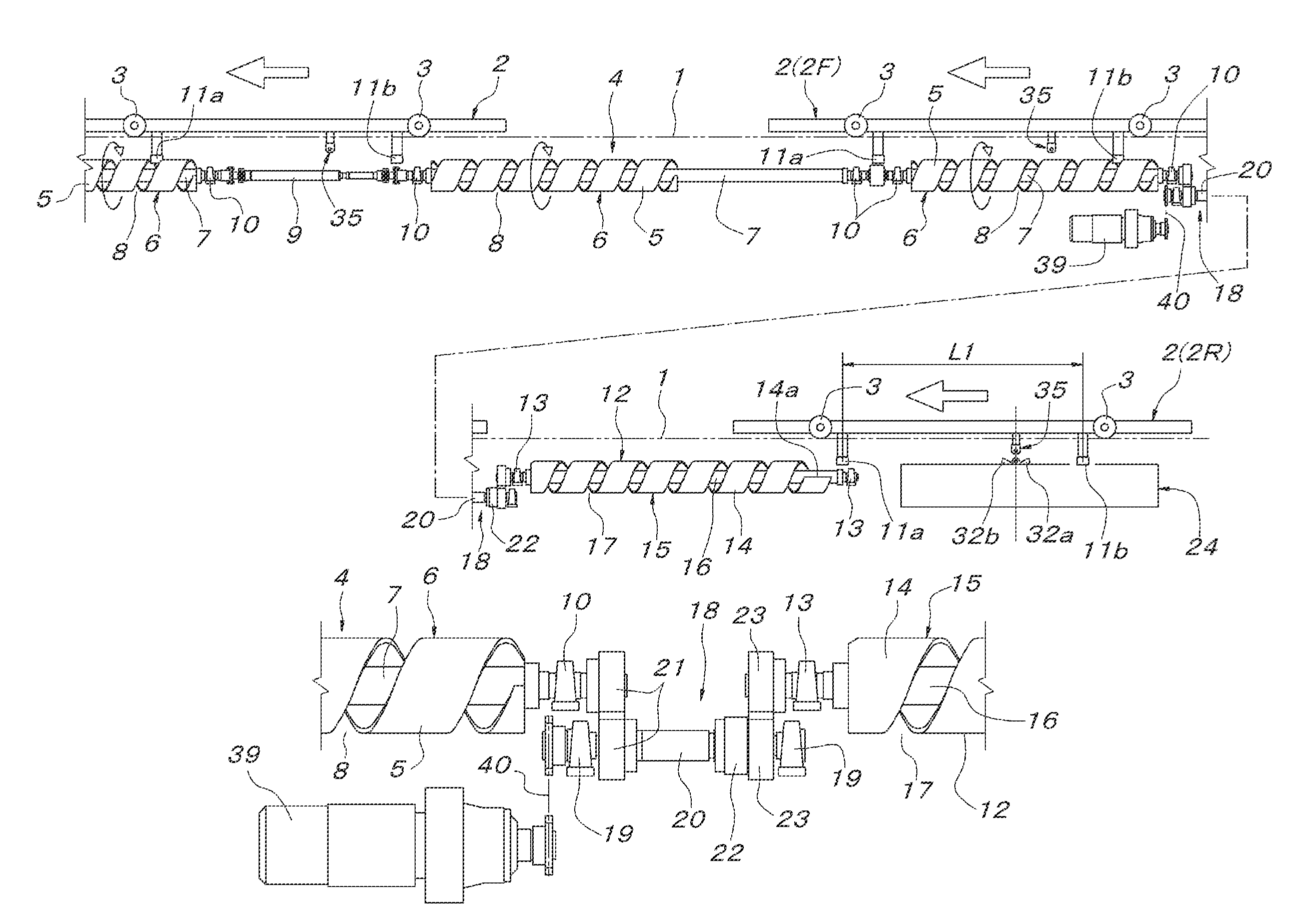
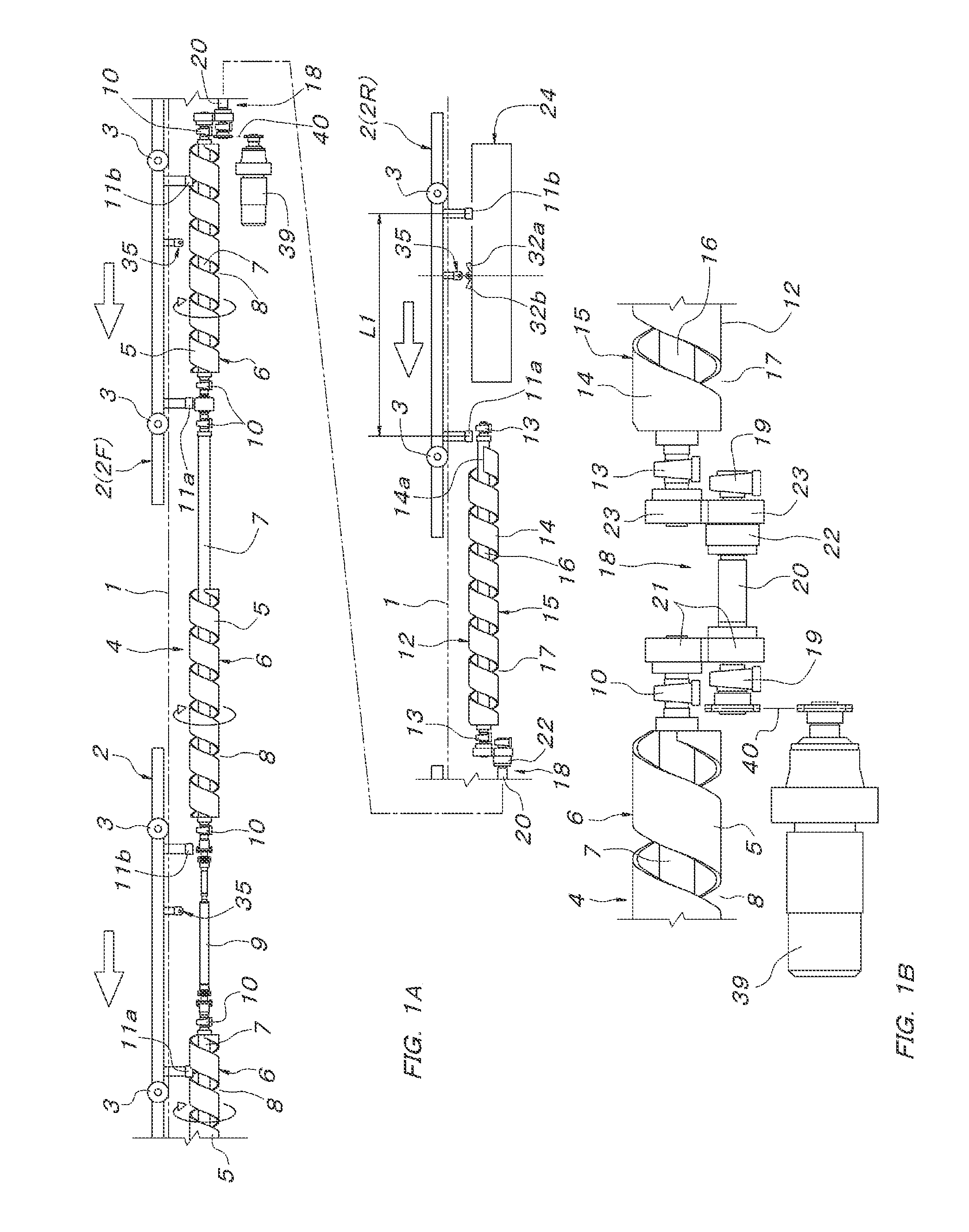
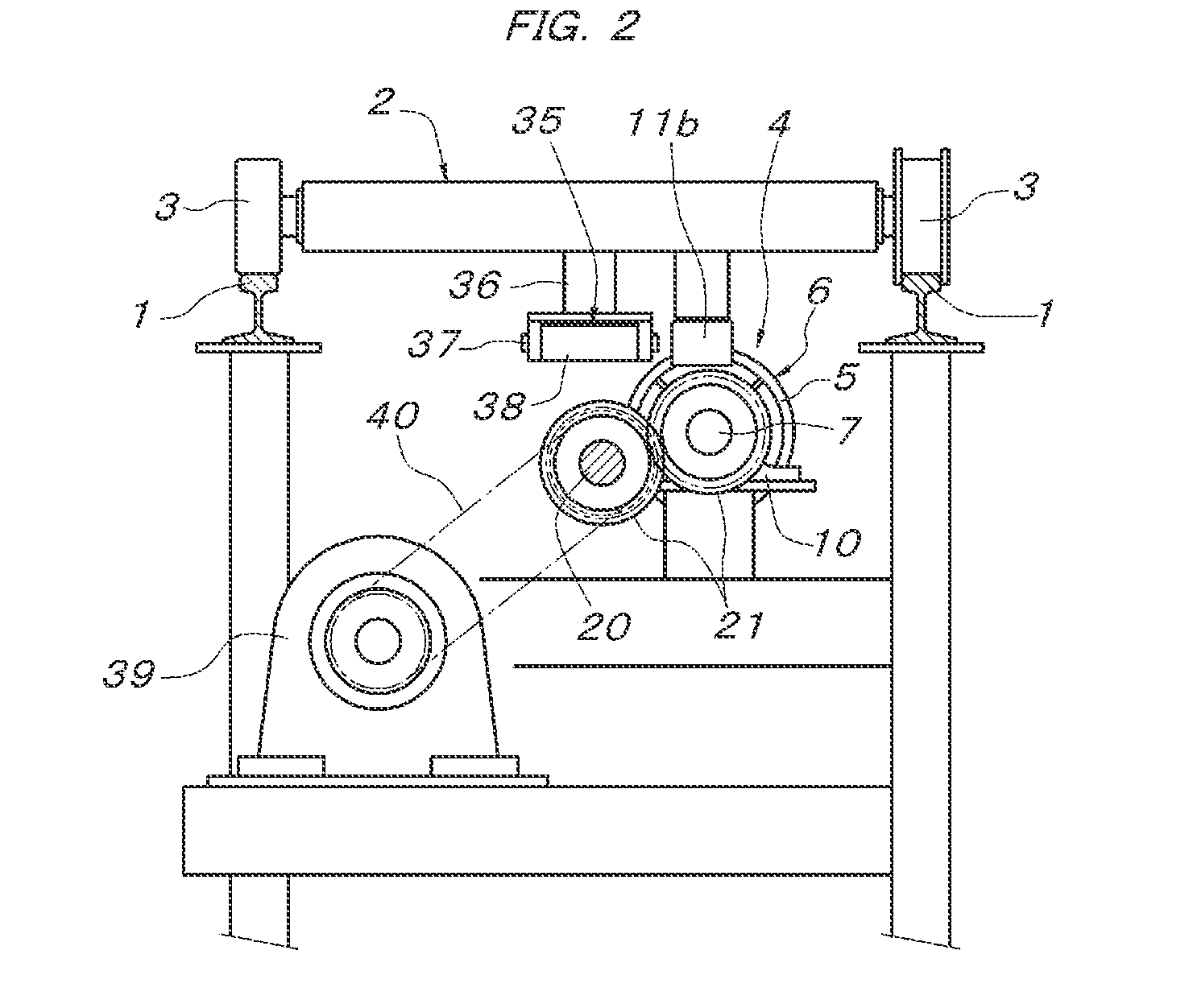
[0025]In FIGS. 1 to 4, reference numeral 1 denotes a pair of left and right guide rails constituting a truck travel path. A conveying truck 2 is supported to travel freely on these guide rails 1 via wheels 3. In the truck travel path, a screw driving area composed of a truck propulsion screw 4 supported in parallel with the truck travel path (the guide rails 1) below the truck travel path is provided. The foregoing truck propulsion screw 4 is constituted of a plurality of screw main bodies 6 in concentric series. Each screw main body 6 is formed by spirally winding a band plate 5 and is supported to a drive shaft 7 concentrically. A spiral groove portion 8 concentric with the drive shaft 7 is formed between adjacent band plates 5. The screw main bodies 6 have a fixed length and are arranged in concentric series at fixed intervals which are substantially equal to the length of the screw main bodies 6 and are an integral multiple of a feeding pitch of the spiral groove portion 8. Betw...


PUM


Abstract

A device for delivering a conveying truck into a screw driving area has a truck delivery screw and a truck propulsion screw which are connected in tandem via a single position electromagnetic clutch and both the screws are configured to rotate in the same phase in the transmission state of the electromagnetic clutch. Two front and back driven rollers are pivotally connected to a conveying truck at an interval at which the driven rollers can engage both screws. A truck delivery mechanism is provided for delivering the conveying truck in the disengaged state of the electromagnetic clutch while rotating the truck delivery screw by the front-side driven roller until the roller arrives at a fixed position in the truck delivery screw.

Description

FIELD OF THE INVENTION[0001]The present invention relates to a conveying truck delivering device for delivering a conveying truck into a screw driving area equipped with a truck propulsion screw to be engaged with a driven roller of the conveying truck and for starting screw drive.BACKGROUND OF THE INVENTION[0002]There is known screw-driven delivery equipment in which a rotationally driven truck propulsion screw is supported along a truck travel path at a screw driving area in the truck travel path and a driven roller to be engaged with the truck propulsion screw is supported to a conveying truck on the truck travel path. In screw-driven delivery equipment described in Japanese Unexamined Patent Application Publication No. 2010-47399, for example, it is known that the truck propulsion screw within the screw driving area is divided and front-rear adjacent truck propulsion screws are linked and coupled to each other via a single position electromagnetic clutch in which engagement is m...

Claims


Application Information

Patent Timeline
Patent Type & Authority Applications(United States)
IPC IPC(8): B65G35/06
CPCB65G35/066B61B13/125B65G33/04B65G33/34
Inventor IBA, TOSHIYUKI
Owner DAIFUKU CO LTD
Learn More