
Alcohol-measuring device with fast operational readiness

a technology of alcohol-measuring device and operational readiness, which is applied in the direction of biochemistry apparatus, diagnostics, medical science, etc., can solve the problems of only being ready to operate, affecting the measurement of alcohol concentration, and undesired delay in the operation of the measuring device, so as to achieve the effect of fast operational readiness

Active Publication Date: 2014-03-06
DRAGER SAFETY
View PDF0 Cites 22 Cited by
  • Summary
  • Abstract
  • Description
  • Claims
  • Application Information

AI Technical Summary

Benefits of technology

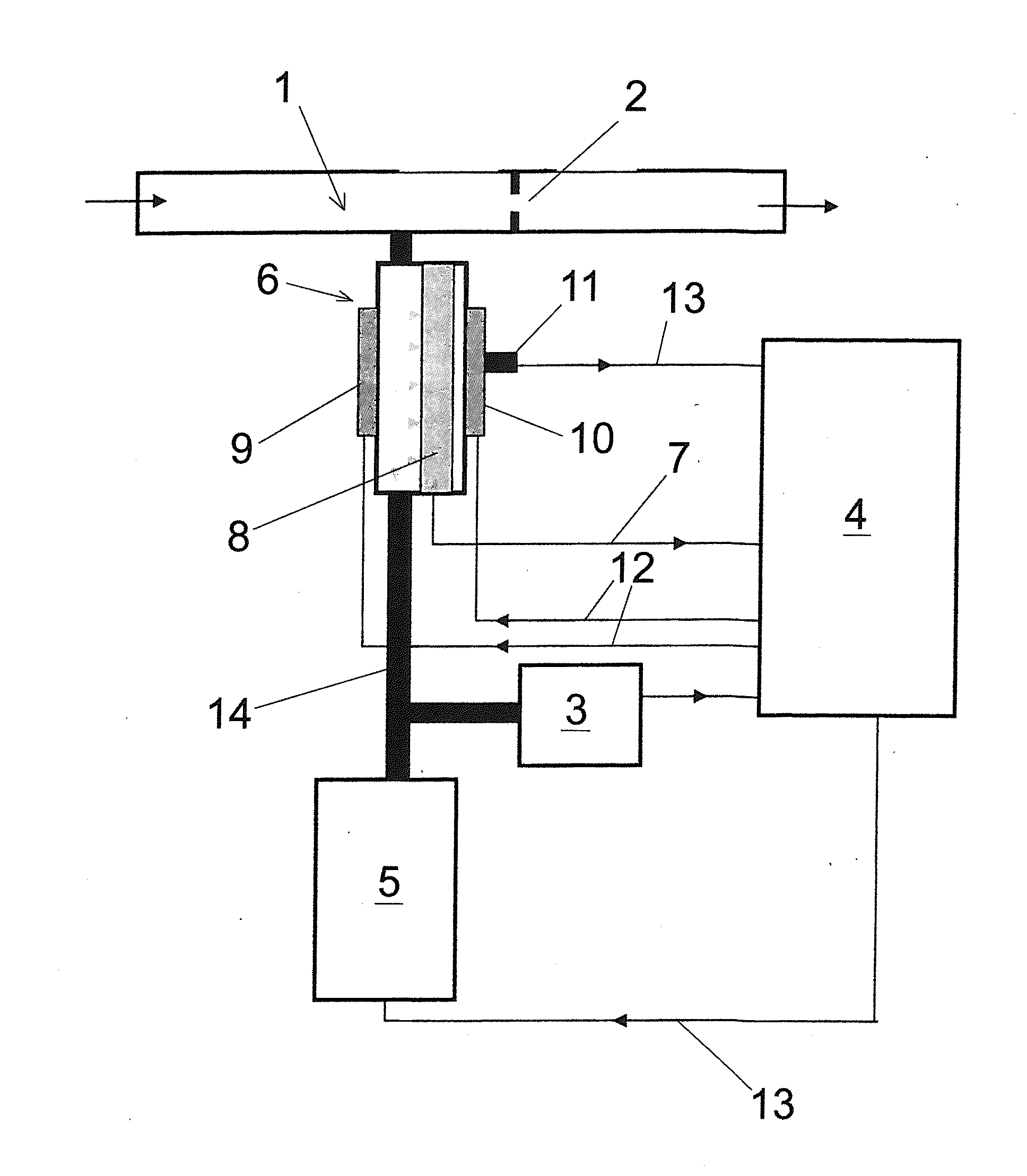
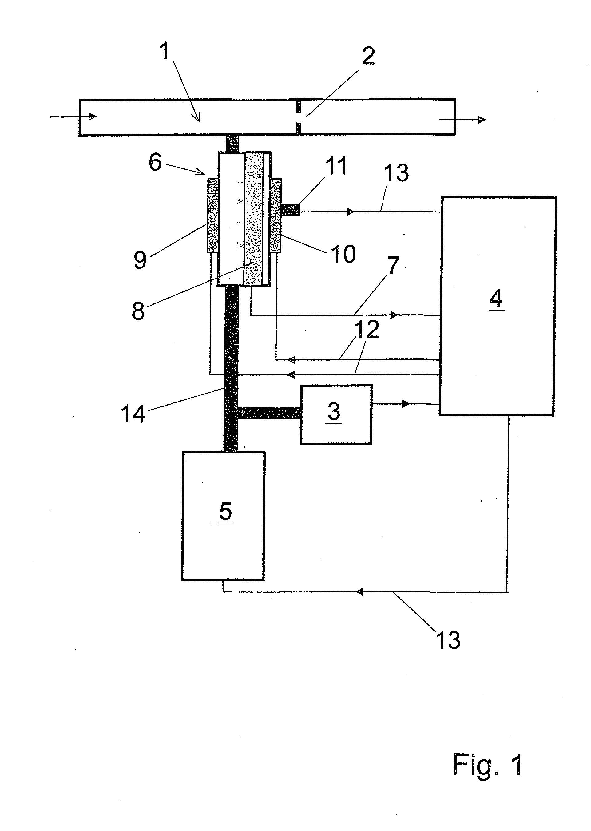
The present invention provides an alcohol-measuring device with an electrochemical sensor that is ready to measure alcohol quickly. This is achieved by using a heating element on both sides of the sensor to quickly heat it up and minimize temperature gradients that can cause distortion of the sensor signal. The device includes a mouthpiece to receive breathing air, an electrochemical sensor to measure alcohol in the air, and a heating arrangement to heat the sides of the sensor to reduce temperature gradients. A control unit is connected to the heating arrangement to control the heat supplied to the sensor. The result is a faster and more accurate alcohol-measuring device.

Problems solved by technology

An essential drawback of the prior-art solution is that in case of heating the electrochemical sensor on one side by means of only a single heating element on the outer side of the sensor or of the sensor housing, the sensor only yields accurate measurement results after a certain time, so that the measuring device is only ready to operate after a rather long time delay.
This current interferes with the measurement of the alcohol concentration, during which the current generated by the reaction of the alcohol molecules is analyzed.
The time needed for the temperature gradient to disappear is often longer than the actual time during which the sensor is heated up and thus it leads to an undesired delay in the measuring device becoming ready to operate.

Method used


Image

  • Alcohol-measuring device with fast operational readiness
  • Alcohol-measuring device with fast operational readiness
  • Alcohol-measuring device with fast operational readiness

Examples


example

[0033]

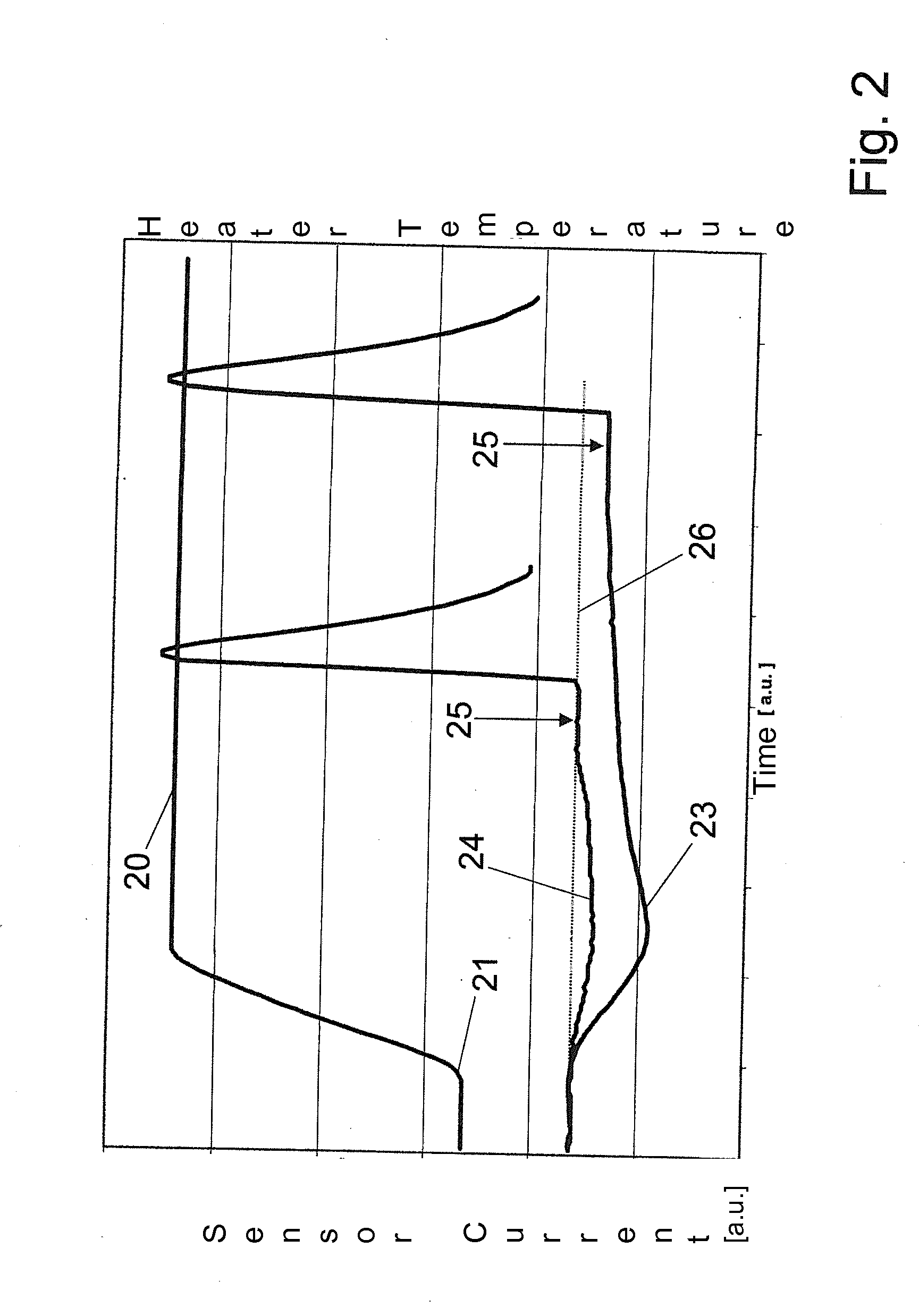
T_startT_sollE_minHeat-up time −5° C.20° C. 30 Wsec20 sec−40° C.45° C.150 Wsec90 sec

The temperature of the heating elements 9, 10 and the quantity of energy flowing into the membrane 8 are determined according to Equation 1 during the heating up. After the desired temperature T_soll and the minimum energy value E_min have been reached, the alcohol-measuring device tests the sensor signal and signals the operational readiness in case of sufficient stability.

[0034]With the introduction of E_min, the evaluation of the heat-up operation becomes independent from the time elapsing until T_soll is reached, because only the energy transferred into sensor 6 is detected independently from the time. This is especially important in interlock systems in which the supply voltage for the heating elements 9, 10 fluctuates greatly depending on the temperature and the state of the vehicle battery. Since the power dissipated in the heating elements is a quadratic function of the voltage, greatly...


PUM

PropertyMeasurementUnit
volumeaaaaaaaaaa
temperatureaaaaaaaaaa

Abstract

An alcohol-measuring device includes a mouthpiece (1), designed to enable a test subject to release breathing air into the mouthpiece, an electrochemical sensor (6), in fluidic connection with the mouthpiece (1) to measure alcohol in the breathing air of the test subject and a control unit. The sensor (6) has at least two heating elements (9, 10), one heating element arranged on the front side and one heating element arranged on the rear side of the sensor (6). The control unit (4) is electrically connected to the heating elements to supply electrical energy for the heating elements. The control unit (4) is set up to heat the heating elements each to a desired temperature. The control unit (4) is also electrically connected to the sensor (6) in order to determine the value of the alcohol concentration in the breathing air of the test subject.

Description

CROSS REFERENCE TO RELATED APPLICATIONS[0001]This application claims the benefit of priority under 35 U.S.C. §119 of German Patent Application DE 10 2012 017 638.4 filed Sep. 6, 2012, the entire contents of which are incorporated herein by reference.FIELD OF THE INVENTION[0002]The present invention pertains to an alcohol-measuring device, which is provided with an electrochemical sensor and is designed to achieve fast operational readiness of the measuring device.BACKGROUND OF THE INVENTION[0003]DE 196 19 169 C2 describes an electrochemical gas sensor with at least two electrodes, with an electrode support and with an electrolyte in a housing made of a material impermeable to the electrolyte: the otherwise closed housing has only one inlet and outlet capillary each for the gas to be measured. Furthermore, a heater and the working electrode are arranged in the housing in the flow path between the inlet capillary and the outlet capillary, wherein the heater forms a gap with the workin...

Claims


Application Information

Patent Timeline
Patent Type & Authority Applications(United States)
IPC IPC(8): G01N27/416
CPCG01N27/4162G01N33/497A61B5/082A61B5/091A61B5/4845A61B5/08G01N27/16
Inventor STOCK, BURKHARDREKOW, JENS
Owner DRAGER SAFETY
Learn More