Flow control proportional valve

a proportional valve and flow control technology, applied in the direction of valve operating means/release devices, process and machine control, etc., can solve the problems of inability to meet the requirements of traditional inability to provide satisfying flow, and inability to meet the requirements of pneumatic and electrically controlled ventilators. to achieve the effect of high repeat precision, simple structure and easy realization

Active Publication Date: 2014-02-27
BEIJING AEONMED
View PDF5 Cites 17 Cited by
  • Summary
  • Abstract
  • Description
  • Claims
  • Application Information

AI Technical Summary

Benefits of technology

The present invention provides a flow control proportional valve that can ensure sufficient gas flow for the normal operation of a ventilator even at low gas pressure. The valve has a simple structure, rapid response speed, and long service life. The coil rack is placed in the magnetic field, and the valve can be controlled by varying the input voltage to achieve precise flow control. The valve has a high repeat precision and a rapid response speed. The shaft sleeet with low friction coefficient improves the smooth motion of the valve and its service life. The airtightly sealing means ensures the precision of gas flow within the valve body and improves safety, reliability, and service life. The sealing ring further improves the sealability of the valve body and safety.

Problems solved by technology

However, an opening area of such proportional valve (i.e., a drift diameter) is relatively small, therefore the output pressure of the driving gas source is generally high in order to meet a flow requirement needed by the pneumatic and electrically controlled ventilator, as a result, the applicability of the pneumatic and electrically controlled ventilator is limited to locations, such as a hospital, where the required sufficient high-pressure driving gas source can be offered.
However, with the increasingly extended applicability of ventilators, the traditional pneumatic and electrically controlled ventilator cannot meet some usage requirements for the ventilator in some specific environment due to its excessive usage limitations.
For example, when the ventilator is used for salvage in some place, such as outdoors, where a high-pressure driving gas source is insufficient or even unavailable, it is difficult to provide a steady and sufficient high-pressure driving gas source to the ventilator, thus the pneumatic and electrically controlled ventilator cannot provide a satisfying flow and therefore cannot work normally.
However, since the turbine has a low trigger sensitivity and long inspiration response time, the electric and electrically controlled ventilator sometimes cannot be well synchronous with the breathing of a patient.
However, since a response speed of the turbine is not fast enough, the service life of the turbine would be affected by frequent acceleration and deceleration for long time of the turbine, thus the application of the electric and electrically controlled ventilator is also restricted.

Method used


Image

  • Flow control proportional valve
  • Flow control proportional valve
  • Flow control proportional valve

Examples


Embodiment Construction

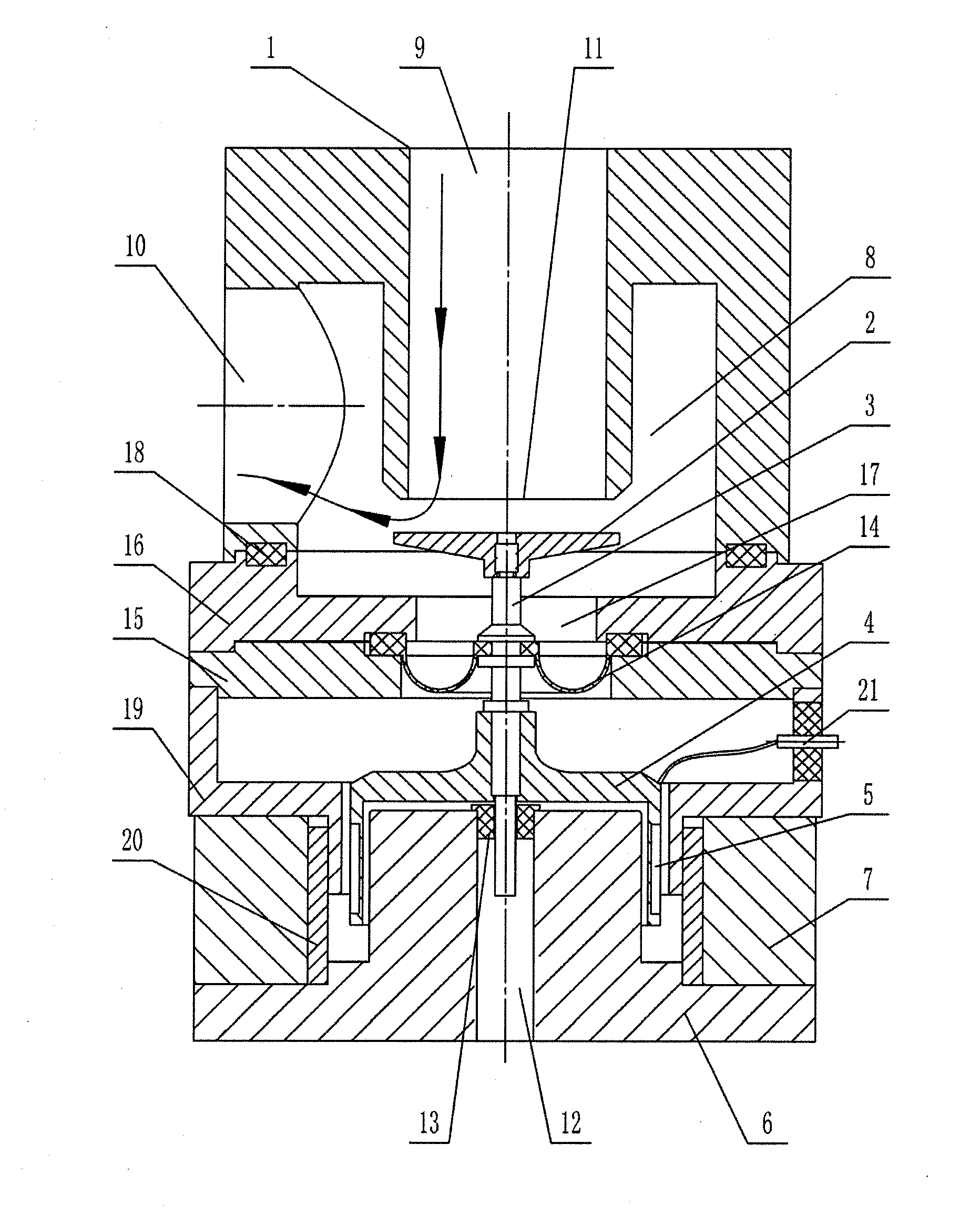
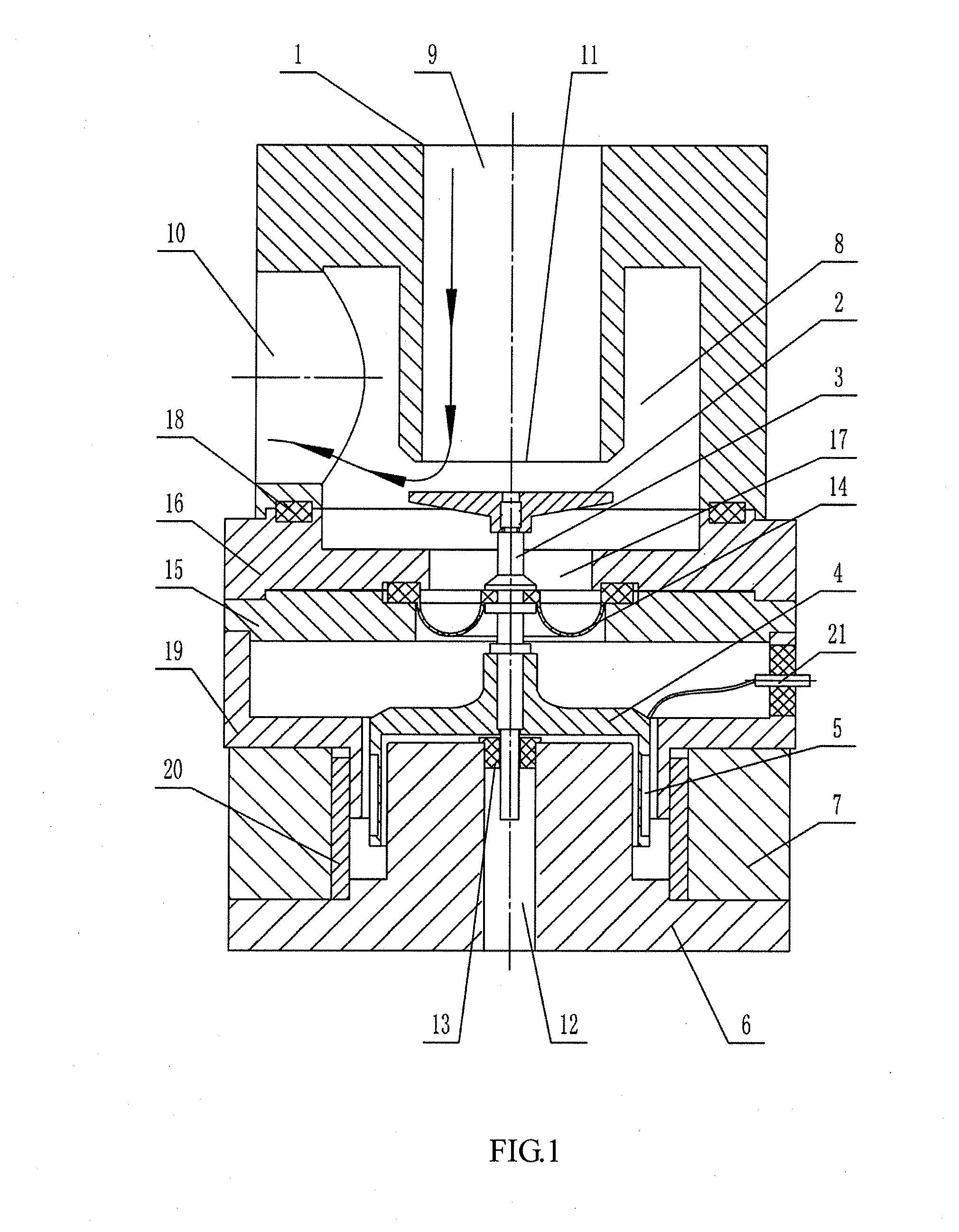
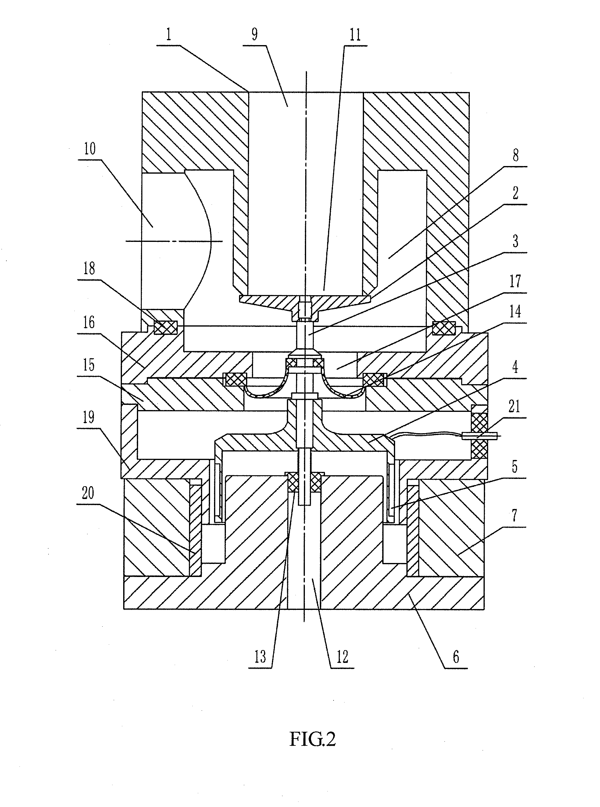
[0022]As shown in FIGS. 1 and 2, a flow control proportional valve in preferred embodiments of the present invention includes a valve body 1 and a valve core, the valve body 1 is provided with an internal cavity 8 which is in communication with a gas inlet 9 and a gas outlet 10 arranged on the valve body 1, and the gas inlet 9 includes a valve port 11 within the cavity 8. A valve core is arranged below the valve body 1, and a valve cover plate 2 is provided on an upper end of the valve core and is placed opposite the valve port 11. The bottom of the valve cover plate 2 is connected with a connecting rod 3, a coil rack 4 fixedly mounted at a lower end of the connecting rod 3 is wound by an enameled wire 5, a magnetic core 6 and a magnet ring 7 are arranged below the coil rack 4, where the magnetic core 6 presents an inverted T-shape structure, and the magnet ring 7 is arranged around the central part of the magnetic core 6 and fixedly mounted on the base part of the magnetic core 6 a...


PUM


Abstract

A flow control proportional valve comprises a valve body and a valve core disposed below the valve body, a valve cover plate is disposed at an upper end of the valve core, the bottom of the valve cover plate is connected to an upper end of a connection rod, a coil rack fixedly mounted at a lower end of the connection rod is wound by an enameled wire which is connected to a power supply unit, a magnetic core and a magnetic ring are disposed under the coil rack, the magnetic ring surrounds the magnetic core, a gap is kept between the magnetic ring and the magnetic core to form a magnetic field, the coil rack is sleeved on the magnetic core and is disposed in the gap.

Description

FILED OF THE INVENTION[0001]The present invention relates to a flow control proportional valve for controlling a large flow at a low pressure state, and more particularly to a flow control proportional valve for a ventilator using a low-pressure driving gas source.BACKGROUND OF THE INVENTION[0002]It is well known that the ventilator is an apparatus that can substitute for, control or change human normal physiological respiration, to increase the pulmonary ventilation volume, improve the respiratory function, decrease breathing power consumption and save the cardiac reserve ability. Such ventilator has become an important instrument for clinically salvaging and treating various respiratory failures as well as providing post-anesthesia and postoperative respiratory support. Ventilators include a pneumatic and electrically controlled ventilator, a pneumatic and pneumatically controlled ventilator, and an electric and electrically controlled ventilator, in terms of their control manners...

Claims


Application Information

Patent Timeline
IPC IPC(8): F16K31/06G05D7/06
CPCG05D7/0635F16K31/0655A61M39/22F16K31/082A61M16/20A61M16/203Y10T137/7761A61M16/206
Inventor SHEN, YOUFANG
Owner BEIJING AEONMED
Why Eureka
Try Eureka