Laser Cutting Method Optimized In Terms Of The Amount of Aerosols

a laser cutting method and aerosol technology, applied in the direction of laser beam welding apparatus, manufacturing tools, facility decommissioning, etc., can solve the problems of no laser cutting method optimized, difficult control of sedimented slag and aerosols in the surrounding environment, and even more undesirable residues, etc., to achieve satisfactory robustness, improve cutting efficiency, and reduce the effect of cutting pressur

Active Publication Date: 2014-02-27
COMMISSARIAT A LENERGIE ATOMIQUE ET AUX ENERGIES ALTERNATIVES
View PDF3 Cites 4 Cited by
  • Summary
  • Abstract
  • Description
  • Claims
  • Application Information

AI Technical Summary

Benefits of technology

[0083]A minimal cut-off pressure is required to ensure the cutting. Thus, for an impact diameter of the laser beam on the piece comprised between 2 and 4 mm, a pressure of 0.08 bars is required to cut out 10 mm of stainless steel. In practice, 0.25 bars is a value that ensures a satisfactory robustness for piece thicknesses below 80 mm. A pressure of 0.8 bars makes it possible to cut out stainless steel pieces up to 100 mm.
[0084]A higher cut-off pressure admittedly improves the productivity of the cutting, by providing a higher limit speed for the same power (a pressure of 0.8 bars thus makes it possible to double the cutting limit speed obtained with the impact pressure of 0.25 bars for thicknesses comprised between 20 and 80 mm), but it reduces the proportion of adherent slag to the profit of sedimented slag and aerosols favouring the evacuation of the molten material and slag which form inside the cutting edge.

Problems solved by technology

Dispersion of sedimented slag and aerosols in the surrounding environment is difficult to control.
It will be easily understood that when laser cutting is used for dismantling nuclear facilities, the residues are even more undesirable, because they contain irradiated or contaminated materials, which are consequently radioactive.
However, the aerosols clog and irradiate the filters, which thus need to be replaced often and treated as waste.
No optimized laser cutting method exists at the present time that makes it possible to limit the production of aerosols.

Method used


Image

  • Laser Cutting Method Optimized In Terms Of The Amount of Aerosols
  • Laser Cutting Method Optimized In Terms Of The Amount of Aerosols
  • Laser Cutting Method Optimized In Terms Of The Amount of Aerosols

Examples


example of application

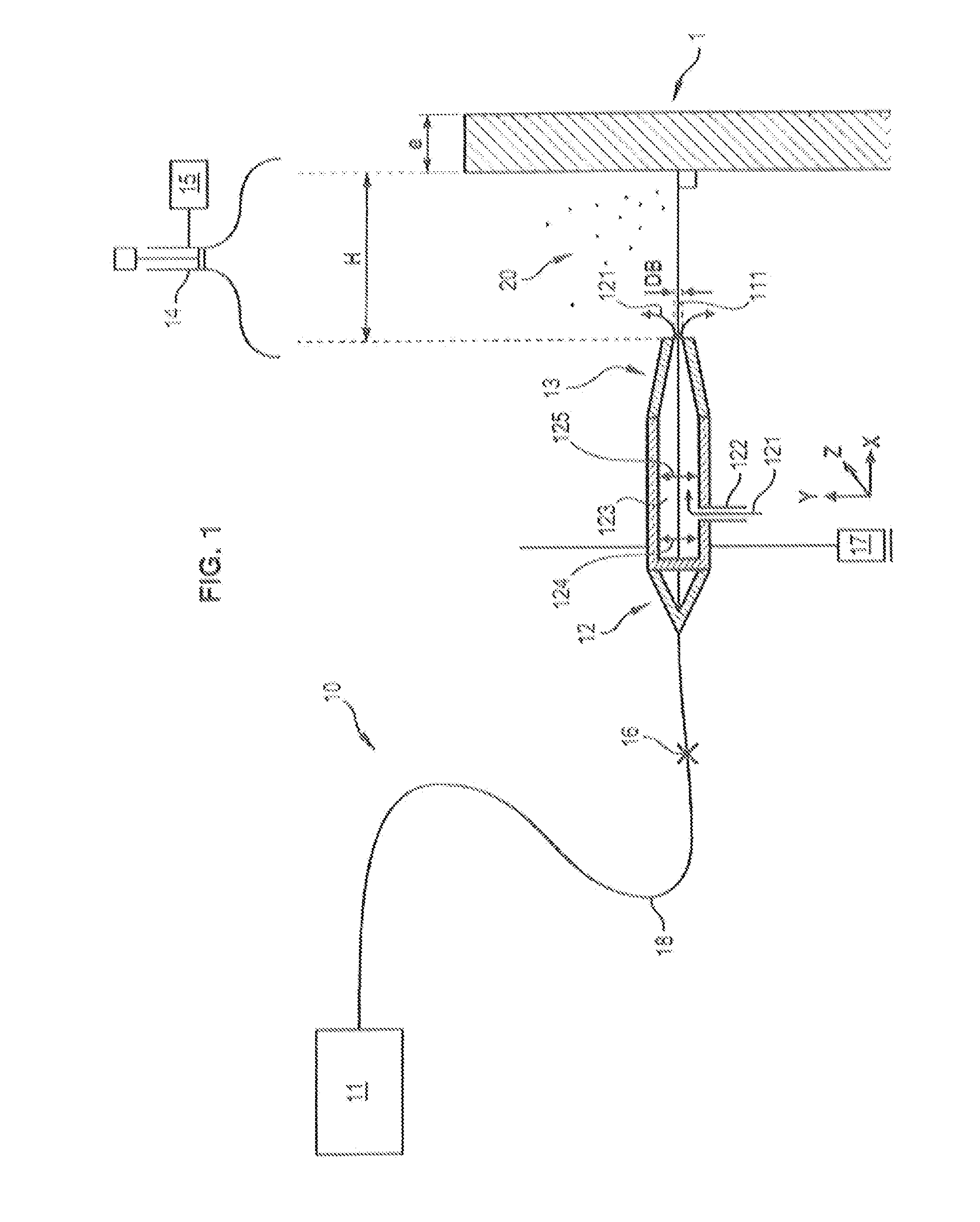
[0142]For a nozzle diameter DB of 3 mm, and a coefficient k of 0.5, and if it is wished to cut a part of a thickness e of 40 mm, the optimal power Popt of the beam 111 is 7.46 kW, i.e. substantially 7.5 kW.

[0143]If, for a same nozzle diameter DB, it is sought to cut the same piece 1 with a coefficient k of 0.7, then the optimal power Popt of the beam 111 is 7.24 kW, i.e. substantially 7.25 kW.

[0144]It will be noted that if it is wished to cut a piece of a thickness e of 50 mm, with a coefficient k of 0.5, then the power Popt is 8.16 kW. In general, the aforementioned type of source 11 has a maximal power of 8 kW. One could then in this case

[0145]either apply the maximal power of 8 kW for the cutting;


PUM

PropertyMeasurementUnit
poweraaaaaaaaaa
cutting power Pdaaaaaaaaaa
thicknessaaaaaaaaaa

Abstract

The invention relates to an optimized laser cutting method for cutting a part from a material by means of a cutting system comprising: a laser source for producing a laser beam having a certain power; and a cutting head comprising an end nozzle for passage of a cutting laser beam, wherein the method comprises: determining a cutting power Pd such that Pd=Max(Popt;λe) where Max is the mathematical operator of the maximum, Popt is an optimal power of the laser beam of the cutting system, which is predetermined in accordance with the part to be cut, and/or with cutting parameters and/or with system parameters, in order to minimize the amount of aerosols produced when the part is cut, λ is a leading coefficient representing the number of kW required for cutting the part per mm of the thickness of the part, and e is the thickness of the part in mm.

Description

GENERAL TECHNICAL FIELD[0001]The present invention relates to an optimized laser cutting method for cutting a part from a material by means of a cutting system comprising[0002]a laser source for producing a laser beam having a certain power, and[0003]a cutting head comprising an end nozzle for the passage of the cutting laser beam.PRIOR ART[0004]An application of lasers for cutting materials, particularly metals, is known.[0005]Laser cutting is very efficient, but produces three types of undesirable residues:[0006]slag adhering to the surface of the cut-out material, in other words solid particles constituted by ejection of molten material from the cutting groove and compounds thereof formed by oxidoreduction as well as accumulation of impurities during the melting of the cut material;[0007]sedimented slag, in other words slag not adhering to the surface of the cut-out material and falling by gravity;[0008]aerosols, in other words solid particles formed by the projection and the vap...

Claims


Application Information

Patent Timeline
Patent Type & Authority Applications(United States)
IPC IPC(8): B23K26/38
CPCB23K26/38B23K26/0626B23K26/14G21D1/003B23K26/08B23K26/36
Inventor CHAGNOT, CHRISTOPHECANNEAU, GAETANPILOT, GUYFAUVEL, SYLVAIN
Owner COMMISSARIAT A LENERGIE ATOMIQUE ET AUX ENERGIES ALTERNATIVES
Why Eureka
Try Eureka