
A tire with radial or bias carcass

a technology of radial or biased carcasses and tires, applied in the field of tires, can solve the problems of tire sidewalls that cannot be reinforced, tire scrapped, carcass components that cannot be retrieved, etc., and achieve the effect of increasing design efficiency

Inactive Publication Date: 2019-01-10
MICHELIN & CO CIE GEN DES ESTAB MICHELIN
View PDF2 Cites 1 Cited by
  • Summary
  • Abstract
  • Description
  • Claims
  • Application Information

AI Technical Summary

Benefits of technology

The patent aims to provide a tire with multiple protuberances that offer an attractive appearance while maintaining the strength of the tire's sidewalls and carcass reinforcement.

Problems solved by technology

However arrangement of these reinforcements on the sidewalls does not allow the sidewalls of the tire to be reinforced so as to withstand lateral knocks, such as kerbing (knocks against a kerb) or in potholes.
Indeed such knocks, which occur at various speeds and / or at various angles of attack, with conventional tire designs may cause damage, sometimes even going so far as to cause the tire to be scrapped.
Furthermore, the current trend to use aluminum rims rather than steel to contribute in particular to the total esthetic of vehicle has the consequence of causing the rupture of the components of the carcass starting from the speed definitely lower when the tire suffers lateral knocks.
Moreover, the current desire to use tires with increasingly short sidewall height has, as yet another consequence, the fact that a knock to such sidewalls causes more intense degradation than the sidewall with taller sidewall height, thus more damaging to the tire.
Such holes generate a plurality of spews on a surface of the protuberance which makes aesthetic of not only the protuberance but also the sidewall of the tire having such protuberances unfavorable.
Further, trimming of such spews after curing is required which degrades manufacturing efficiency of such tire.
This small projected line clearly impact unfavorably aesthetic of the protuberance and the tire.
The air evacuation from the molding element may also be achieved for example by making an outermost face of the protuberance with an smooth inclined and / or curved surface which a height of such protuberance would be maximal in such outermost face, but air evacuation efficiency is still not sufficient.

Method used


Image

  • A tire with radial or bias carcass
  • A tire with radial or bias carcass
  • A tire with radial or bias carcass

Examples


Embodiment Construction

[0070]Preferred embodiments of the present disclosure will be described below referring to the drawings.

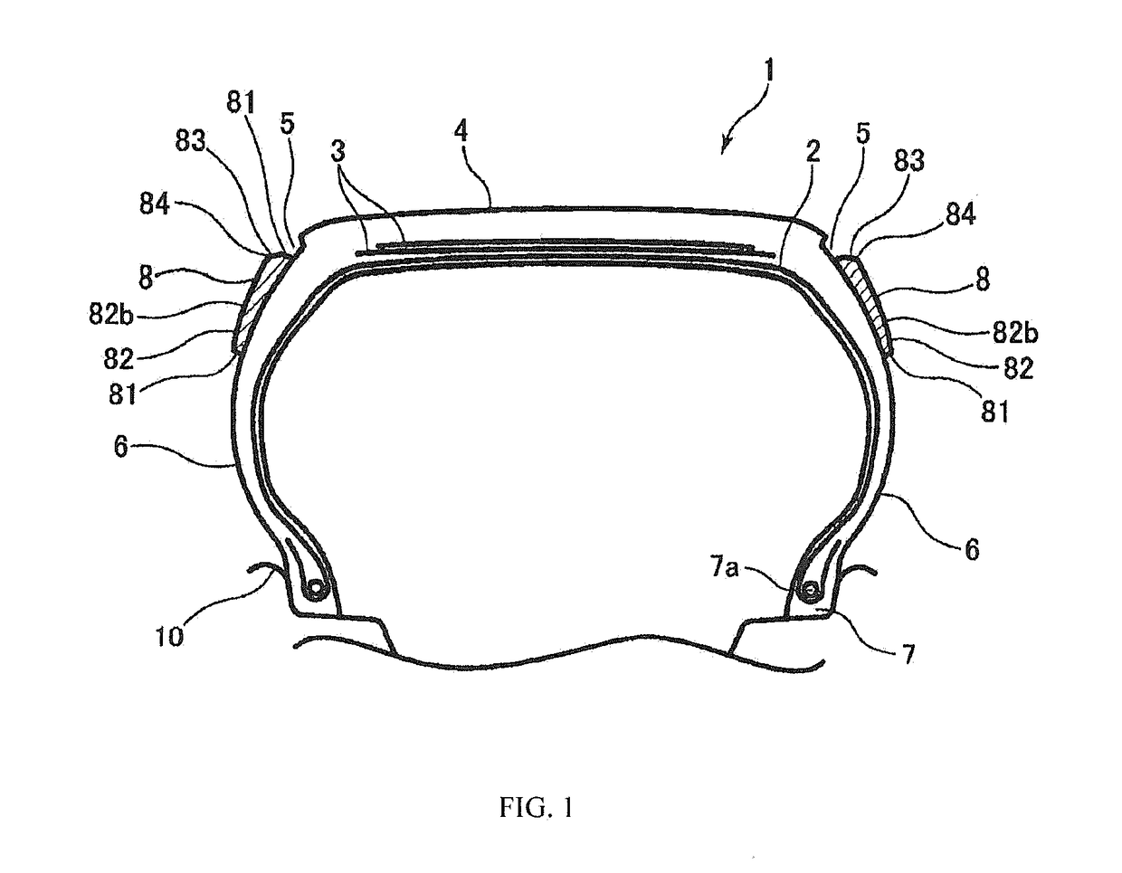
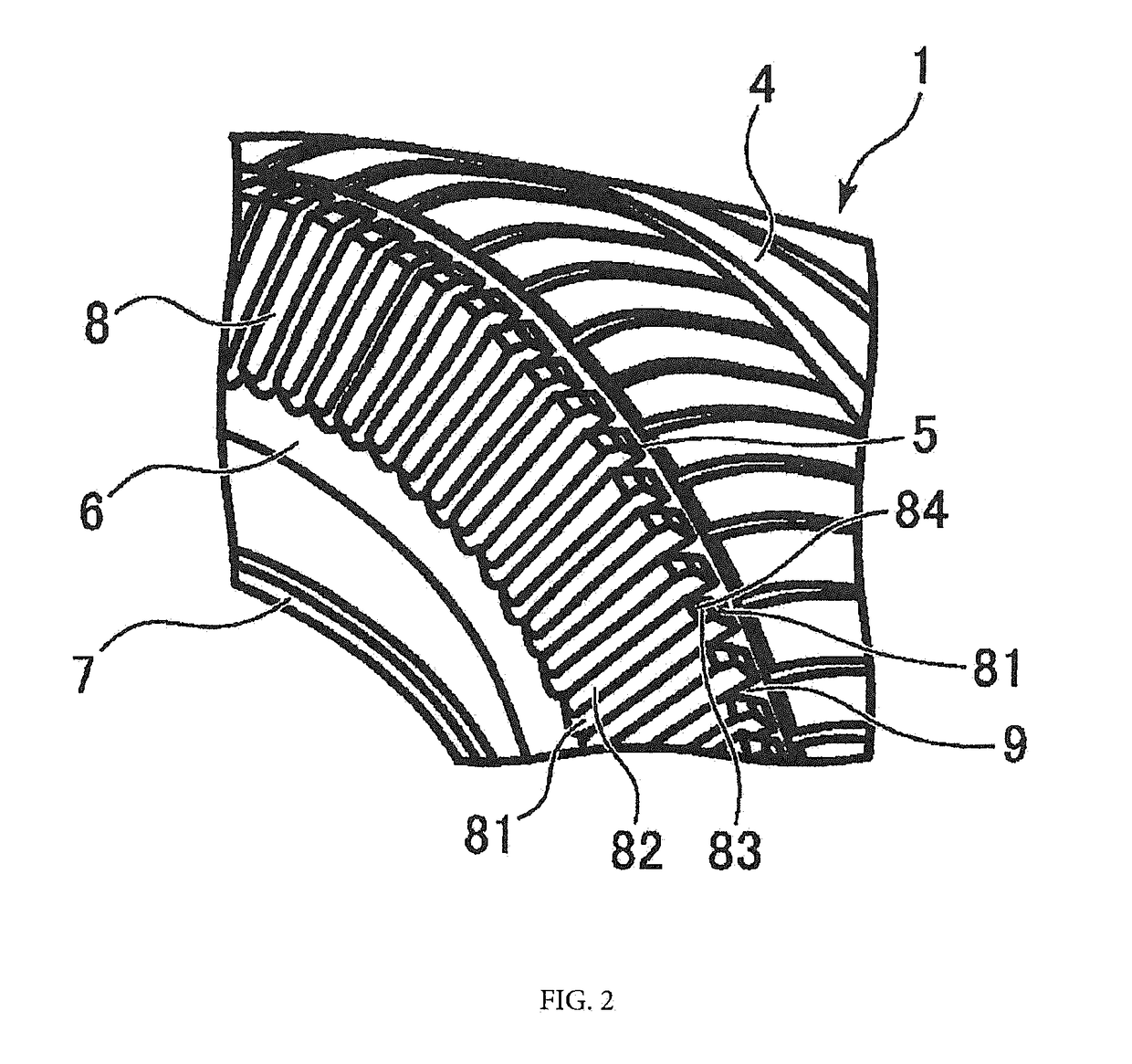
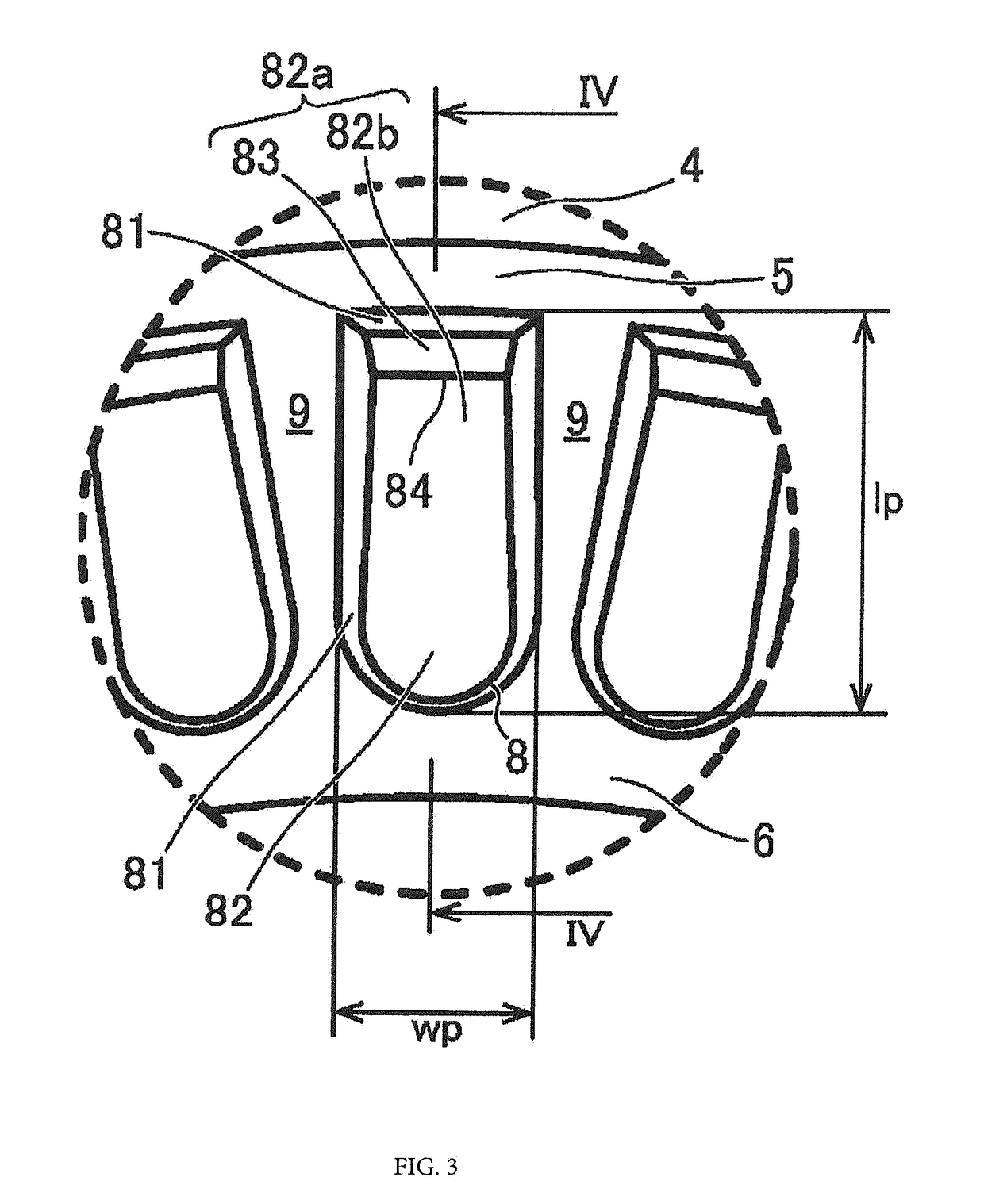
[0071]A tire according to a first embodiment of the present disclosure will be described referring to FIGS. 1, 2, 3 and 4. FIG. 1 is a schematic cross sectional view of a mounted rolling assembly comprising a rim 10 and a tire 1 according to the first embodiment of the present disclosure. FIG. 2 is a schematic perspective view of a portion of a tire 1 according to the first embodiment of the present disclosure. FIG. 3 is an enlarged schematic view of a portion of sidewall 6 according to the first embodiment of the present disclosure. FIG. 4 is a cross sectional view taken along line IV-IV in FIG. 3.

[0072]The tire 1 having dimension 205 / 55R16 and comprises a carcass reinforcement 2, a crown reinforcement 3 being disposed radially outward of the carcass reinforcement 2, a tread 4 being placed radially outward of the crown reinforcement, the tread 4 being connected by two sidewalls 6...


PUM


Abstract

The tire has a carcass reinforcement. A crown reinforcement is disposed on the carcass reinforcement and is made up reinforcing elements. A tread is placed on the crown reinforcement and has two axial ends. At least one of the axial ends has a circumferential groove. The tread is connected by sidewalls to bead zones, each comprising a reinforcing element. At least one sidewall protuberances alternating with voids. Each protuberance has a height hp, a length lp and a width wp and a base part which has a height hb and is formed on the exterior surface of the sidewall and a top part which extends outwardly from the base part and has a top surface. The top surface has an inclined face and a remaining face connected to the inclined face by a connecting part. A height hp of the protuberance is maximal at the connecting part.

Description

CROSS-REFERENCE TO RELATED APPLICATIONS[0001]The present application claims priority to PCT International Patent Application Serial No. PCT / JP2015 / 086593, filed Dec. 25, 2015, entitled “A TIRE WITH RADIAL OR BIAS CARCASS”.BACKGROUND OF THE INVENTION1. Field of Invention[0002]The present invention relates to a tire, in particular to a tire with radial or biased carcass.2. Related Art[0003]Radial tires are gradually imposed on various markets, notably the market for passenger car tires. This success is due in particular to the endurance, comfort and low rolling resistance qualities of radial technology.[0004]The principal parts of a tire are a tread, sidewalls and beads. The beads are intended to come into contact with the rim. In a tire with radial technology, each principal component constituting the tire, namely the tread, the sidewalls and the beads, has well separated functions each other, and therefore has a well-known specific constitution.[0005]A radial tire is essentially rei...

Claims


Application Information

Patent Timeline
Patent Type & Authority Applications(United States)
IPC IPC(8): B60C13/02
CPCB60C13/02B60C2011/0341B60C11/03B60C11/01B60C2011/013
Inventor YOKOKAWA, KAZUTAKASEII, TOMOHIRONOMURA, MASAYOSHI
Owner MICHELIN & CO CIE GEN DES ESTAB MICHELIN
Learn More