
Conveying appliance with valve locating function for use during percutaneous aortic valve replacement operation

a technology for conveying appliances and aortic valves, applied in the field of medical appliances, can solve problems such as shortened lifespan and reduced living quality

Inactive Publication Date: 2014-02-20
CAI JING +1
View PDF1 Cites 20 Cited by
  • Summary
  • Abstract
  • Description
  • Claims
  • Application Information

AI Technical Summary

Benefits of technology

The present invention provides a conveying appliance with valve locating function for use during percutaneous aortic valve replacement operation. The appliance can prevent valve stent dislodgement and adjust the position of the valve stent, thus increasing the success rate of the operation, reducing the operation difficulty, relieving the pain of the patients, and lowering the risk of the procedure and the medical cost. The appliance is simple in structure, convenient in manufacture and easy to implement by appropriate modification to the conveying rod of prior art.

Problems solved by technology

Usually, patients with serious aortic valve stenosis are heavily insufficient of left ventricular function, which is accompanying with decreased living quality and shortened lifespan, thus requires effective treatment.
One of the factors that hinder the development of the percutaneous aortic valve replacement technology is the difficult control during locating the appliances for implantation, it may result in dropping of the instruments when released or results in inaccurate positioning, which will heavily influence the success rate of the procedure and the control of postoperative complications.

Method used


Image

  • Conveying appliance with valve locating function for use during percutaneous aortic valve replacement operation
  • Conveying appliance with valve locating function for use during percutaneous aortic valve replacement operation
  • Conveying appliance with valve locating function for use during percutaneous aortic valve replacement operation

Examples


Embodiment Construction

[0017]Hereinafter the present invention will be described in details with reference to the drawings and embodiment.

[0018]Please refer to FIG. 1-FIG. 3.

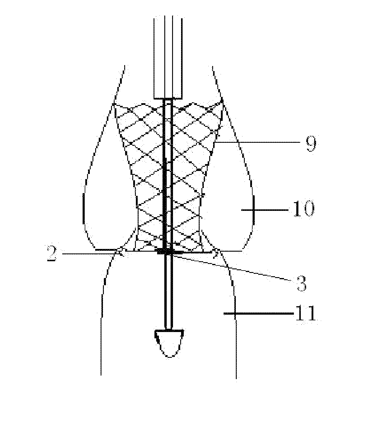
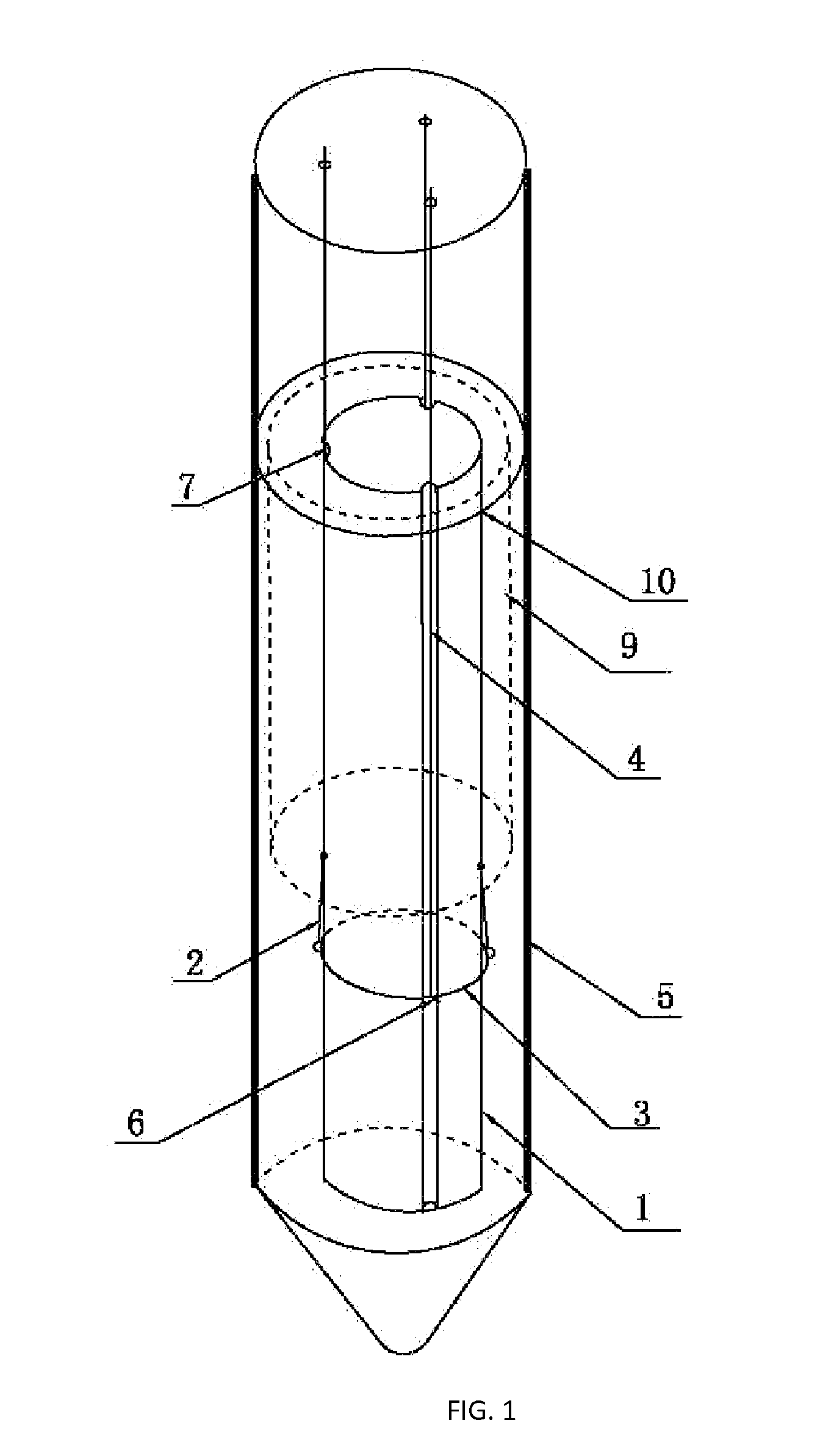
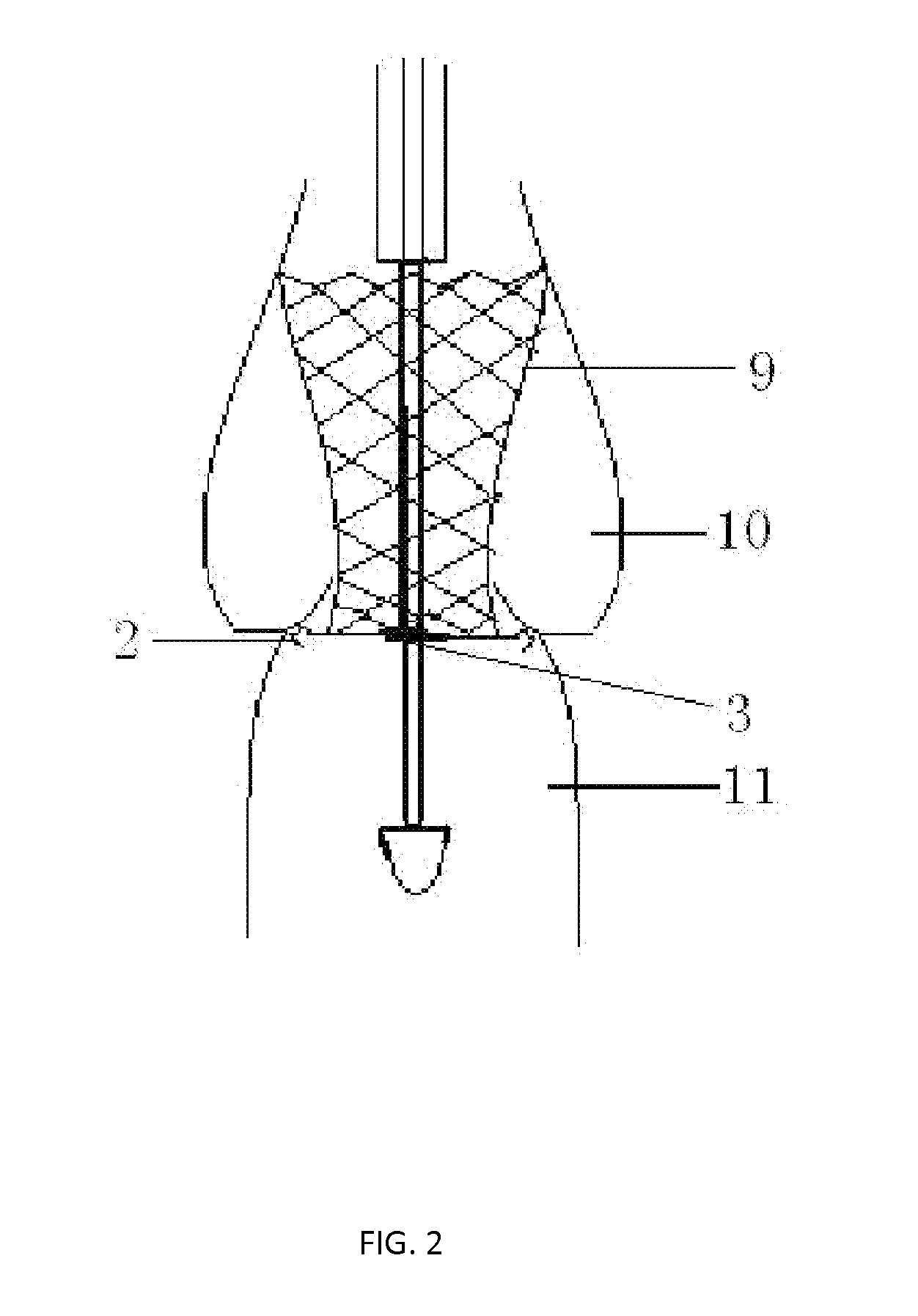
[0019]The conveying appliance with valve locating function for use during percutaneous aortic valve replacement operation mainly comprises conveying rod 1, sheath pipe 5, locating rod 2, round ring 3 and round ring operating rope 4. As shown in FIG. 1, the conveying rod 1 is hinged on the distal end (the end located in the human body, i.e., the lower end) of the conveying rod 1 by means of fixed hinge; the tail end of the locating rod 2 is designed as round arc-shaped or round ring-shaped hook so as to prevent from injuring the human body due to a sharp tip; the cross section of the rod body of the locating rod 2 is in a shape of round arc with smooth edge; the assembled hook-like portion shall have a diameter smaller than the inner diameter of the conveying sheath pipe 5; the locating rods 2 are capable of stretching (like opening up...


PUM


Abstract

A conveying appliance with valve locating function for use during percutaneous aortic valve replacement operation includes a conveying rod (1), a sheath pipe (5), a round ring (3), at least two locating rods (2) and at least two round ring operating ropes (4). The round ring (3) is sleeved on the lower end of the conveying rod (1) and located in the conveying sheath pipe (5). An end of the locating rod (2) is hinged on the conveying rod (1) and the hinge point is located on the upper portion of the round ring (3). A lower end of the round ring operating rope (4) is provided with a structure for supporting the round ring (3) or is directly connected with the round ring (3). An upper end of the round ring operating rope (4) extends out of a human body along the axial direction of the conveying rod (1). The appliance can locate the implanted valve in a better manner so as to increase the success rate of percutaneous aortic valve replacement operation and reduce the operation difficulty and the postoperative complications. The appliance reduces the pain and the risk of the operation, and lowers the medical cost.

Description

FIELD OF THE INVENTION[0001]The present invention relates to a medical appliance, especially a conveying appliance for precisely locating a valve stent during percutaneous aortic valve replacement operation, and in more particular, to a conveying appliance with valve locating function for use during percutaneous aortic valve replacement operation.BACKGROUND OF THE INVENTION[0002]At present, the statistical data from the related art show that the disease incidence of aortic valve stenosis attributed to aortic valve calcification has reached 2% to 7% among elderly people over 65 years old, and is becoming increasingly higher with age. Usually, patients with serious aortic valve stenosis are heavily insufficient of left ventricular function, which is accompanying with decreased living quality and shortened lifespan, thus requires effective treatment. Until now, artificial aortic valve replacement by means of surgical operation is still the preferred treatment for patients subjected to ...

Claims


Application Information

Patent Timeline
Patent Type & Authority Applications(United States)
IPC IPC(8): A61F2/24
CPCA61F2/2427A61F2/2436A61F2/2439
Inventor KONG, XIANGQINGCAO, JING
Owner CAI JING
Learn More