Eureka AIR delivers breakthrough ideas for toughest innovation challenges, trusted by R&D personnel around the world.

Low voltage plug and play display system

Active Publication Date: 2014-02-13
SUNGAL
View PDF6 Cites 5 Cited by
  • Summary
  • Abstract
  • Description
  • Claims
  • Application Information

AI Technical Summary

Benefits of technology

The present invention ensures that the electricity-bearing elements of a display system are insulated from other components, reducing the risk of shock or fire hazard. The electric source is low voltage (12-24 V) DC current, which prevents any stray voltage from escaping to other elements of the display system.

Problems solved by technology

This lighting method, however, generally prohibits the flexibility associated with modular shelving.
More particularly, this shelf structure generally will not allow for disconnecting a shelf from a first location on a support structure and connecting the shelf at a second different location on the support structure.
In addition, the above shelving systems are based on relatively high voltage AC power sources that introduce excess wiring, resulting in somewhat complex wiring on the shelves themselves and / or the use of “step-down” transformers or ballasts to cut down the voltage between the electric source and the lights.
In addition, the electrical connections of the prior art shelving systems are not completely insulated from the shelving components themselves, and offer opportunities for electrical shock to shoppers and employees placing inventory on the shelves and / or moving the shelves from one location to another.
Moreover, the electric source is low voltage (12-24 V) DC current, so that even if any stray voltage were to escape to other elements of the display system, the risk of shock or fire hazard is extremely low.

Method used


Image

  • Low voltage plug and play display system
  • Low voltage plug and play display system
  • Low voltage plug and play display system

Examples


Embodiment Construction

[0046]The present disclosure will now be described in more detail with reference to the specific embodiments shown in the Figures. In the description of the specific embodiments in the Figures that follows, like elements will be denoted by like reference numbers.

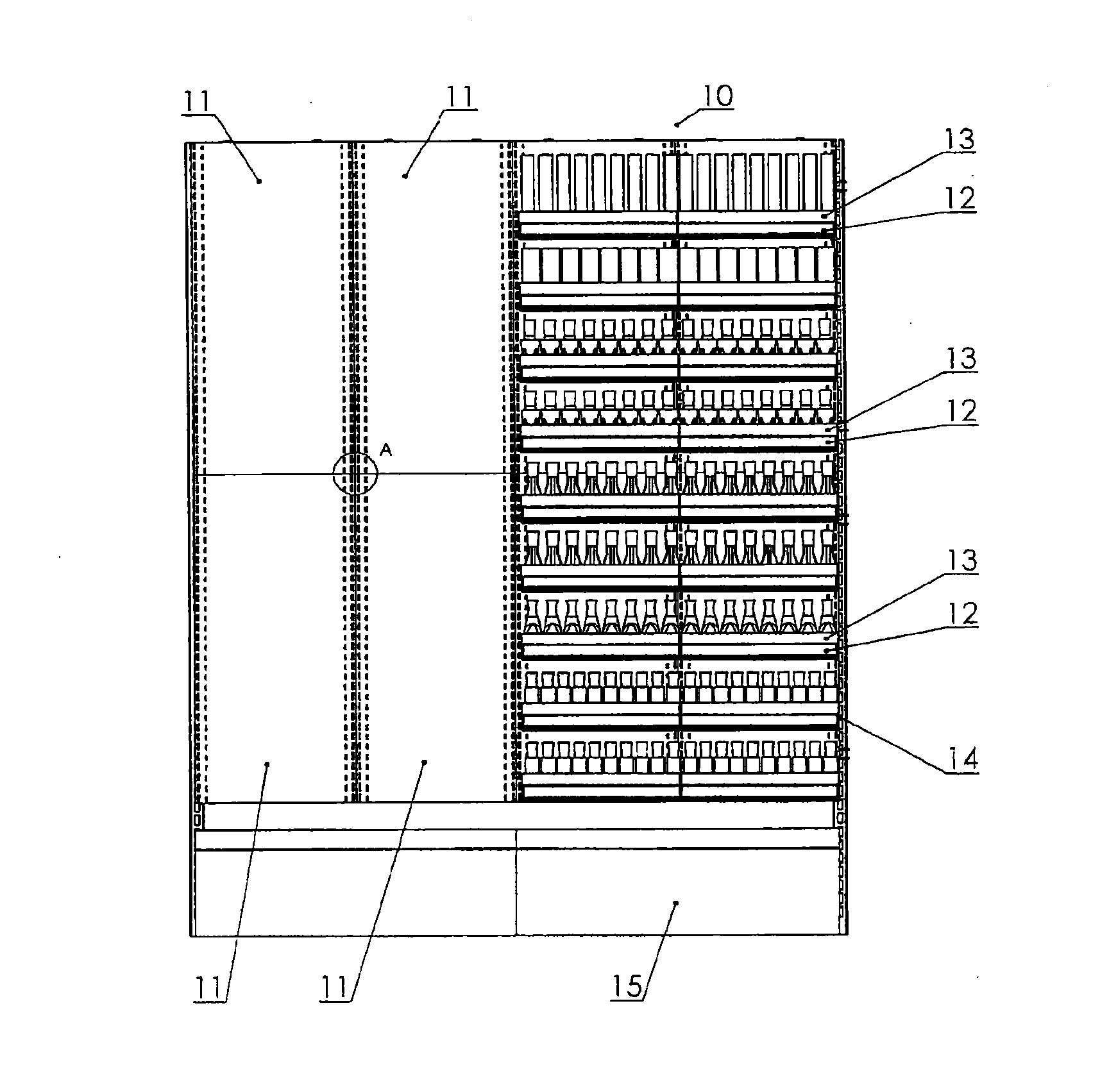
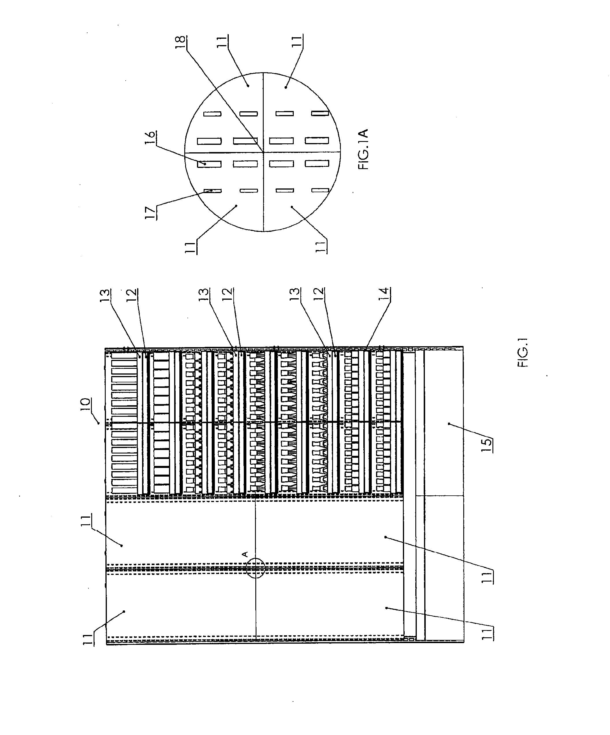
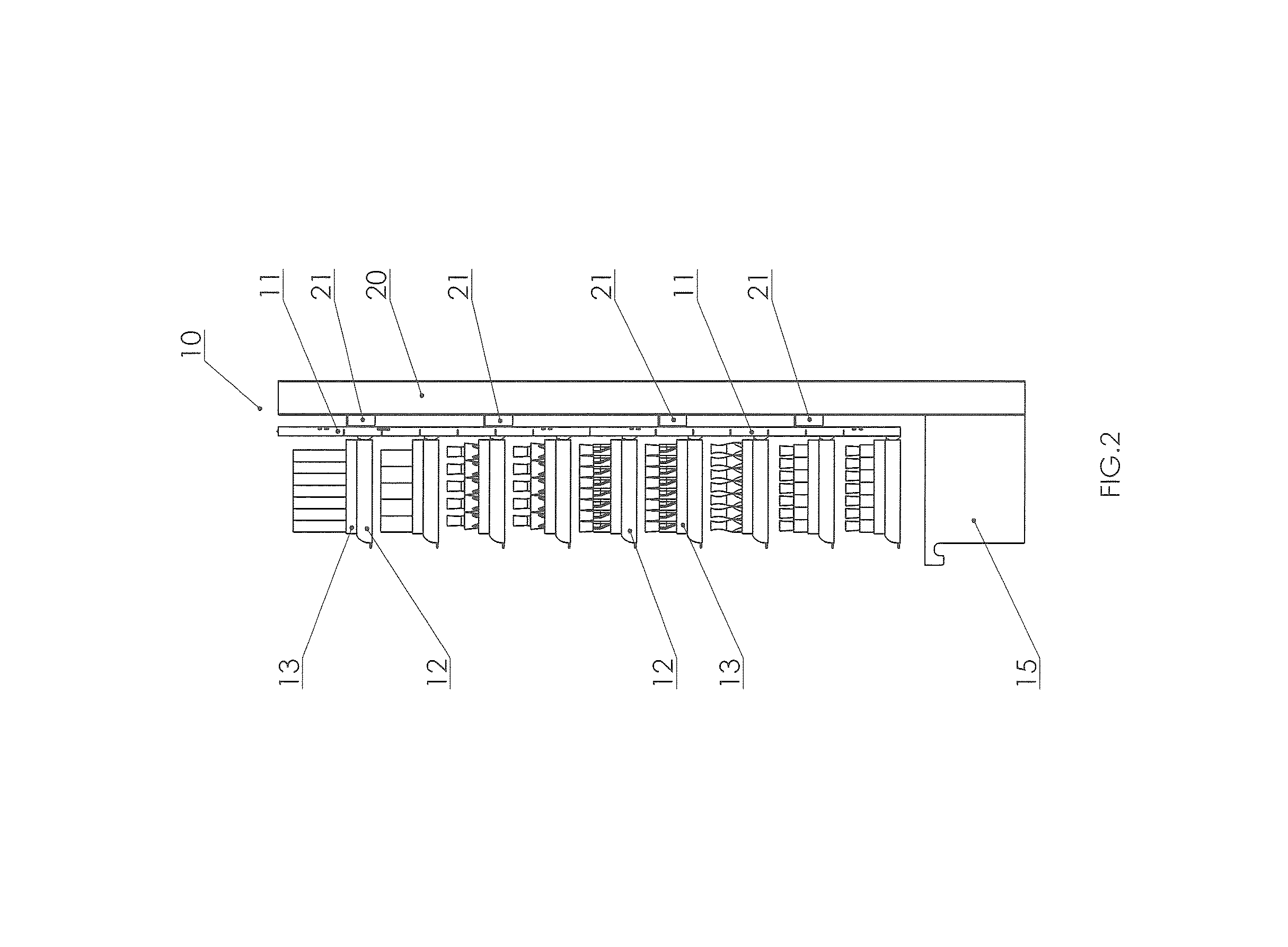
[0047]FIG. 1 shows a wall display unit 10 having connected wall panels 11. Hanging on wall panels 11 of wall display unit 10 are various carry trays 12 having insert trays 13 therein, that will be described in more detail in conjunction with other Figures. Wall panels 11 of wall display unit 10 are connected to standards 14 disposed behind standard slots 16 (see, FIG. 1a). Deck 15 is part of gondola 20, shown in FIG. 2. FIG. 1A shows, in enlarged view, section “A” of FIG. 1. In FIG. 1A four wall panels 11 are joined at junction 18 as will be more fully described hereinafter. As is shown in FIG. 1A, each wall panel has rows of generally parallel disposed slots, standard slots 16 and connector tab slots 17. Standard slots 16 a...


PUM

PropertyMeasurementUnit
Lengthaaaaaaaaaa
Electrical conductoraaaaaaaaaa
Widthaaaaaaaaaa

Abstract

Disclosed are display systems comprised of at least one wall panel and at least one shelf comprising a light fixture, the wall panel having two rows of parallel slots, one set of parallel slots (either on the wall panel or uprights adjacent to the wall panel), providing cooperative access by support brackets disposed on the shelf for supporting the shelf, the support brackets not carrying any of the electrical circuitry for the light fixture, one other set of parallel slots providing cooperative access for electrical contact elements disposed on the shelf to an electric source element disposed on the wall panel and providing electricity to the light fixture. Also disclosed are wall panels, shelves and lighting devices that may be used, alone or in combination, for new installations or in retrofitting existing display systems.

Description

CROSS-REFERENCED APPLICATION[0001]This application claims priority to U.S. Provisional Application Ser. No. 61 / 680,987, filed on Aug. 8, 2012, that is incorporated herein in its entirety by reference thereto.BACKGROUND[0002]1. Field of the Disclosure[0003]The present disclosure relates generally to a display system having a lighting mechanism for illuminating an item below that is on display. The display system includes at least a removable shelf and wall panel and may include other structures for display purposes. More particularly, the present disclosure relates to an illuminated display system. Preferably, the display system utilizes light emitting diode (LED) lighting as part of the display system.[0004]2. Description of Related Art[0005]A typical method of lighting shelves includes lighting connected to the shelves. These shelving and lighting structures generally enclose internal wiring and lighting that may be used to illuminate items on the shelves. This lighting method, how...

Claims


Application Information

Patent Timeline
IPC IPC(8): A47F5/00F21V33/00B23P19/00
CPCA47F5/0018F21V33/0012B23P19/00A47F3/001A47F5/103Y10T29/49826
Inventor SUN, YEYANG
Owner SUNGAL
Why Eureka
Eureka Blog
Learn More